Wiring
4.3 Terminal and block diagrams
CPU 1512C-1 PN (6ES7512-1CK00-0AB0)
Manual, 09/2016, A5E35306440-AB
71
Terminal and block diagrams
4.3.1
Block diagram of the CPU part
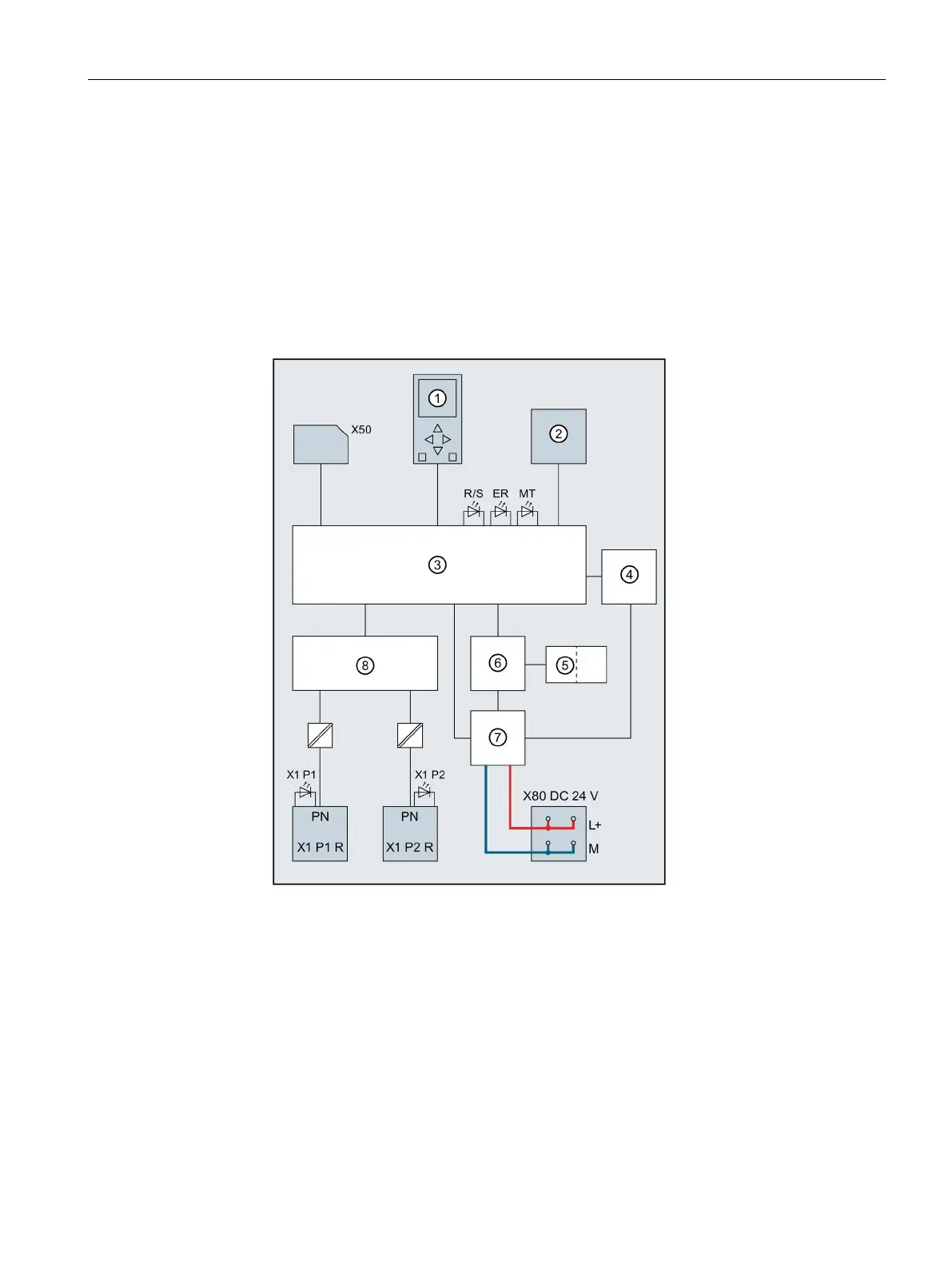
Block diagram
The following figure shows the block diagram of the CPU part.
RUN/STOP/MRES mode selector
PROFINET interface X1 port 1
PROFINET interface X1 port 2
Interface to on-board I/O
Interfaces to the backplane bus
RUN/STOP LED (yellow/green)
Figure 4-2 Block diagram of the CPU part
 Loading...


