Wiring
4.3 Terminal and block diagrams
CPU 1512C-1 PN (6ES7512-1CK00-0AB0)
92 Manual, 09/2016, A5E35306440-AB
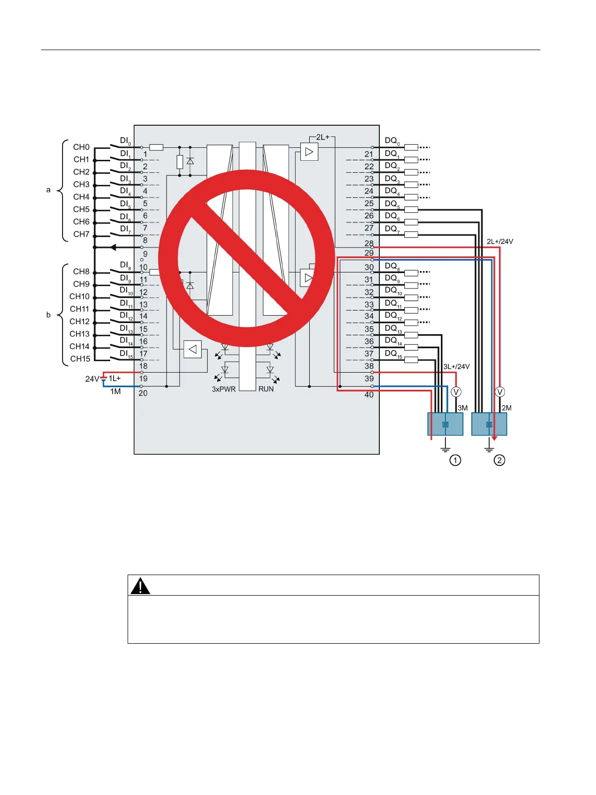
The figure below shows the current flow with correct wiring when a potential difference exits
between the grounding points.
Grounding point functional earth 1 (FE 1)
Grounding point functional earth 2 (FE 2)
Figure 4-20 Potential difference using the digital on-board I/O X11 as an example
Equipotential bonding occurs via terminals 30 and 40. When a potential difference exists
between the grounding points FE1 and FE2, the compensating current flows via terminals 30
and 40.
Current flow with faulty wiring
In the event of a potential difference, the current can be very high, depending on the
potential conditions, and lead to the destruction of the module.
 Loading...


