Latching
2.4 Testing your circuit
Getting Started - Advanced
18 Training Documents, 09/2007, A5E01469795B
2.4 Testing your circuit
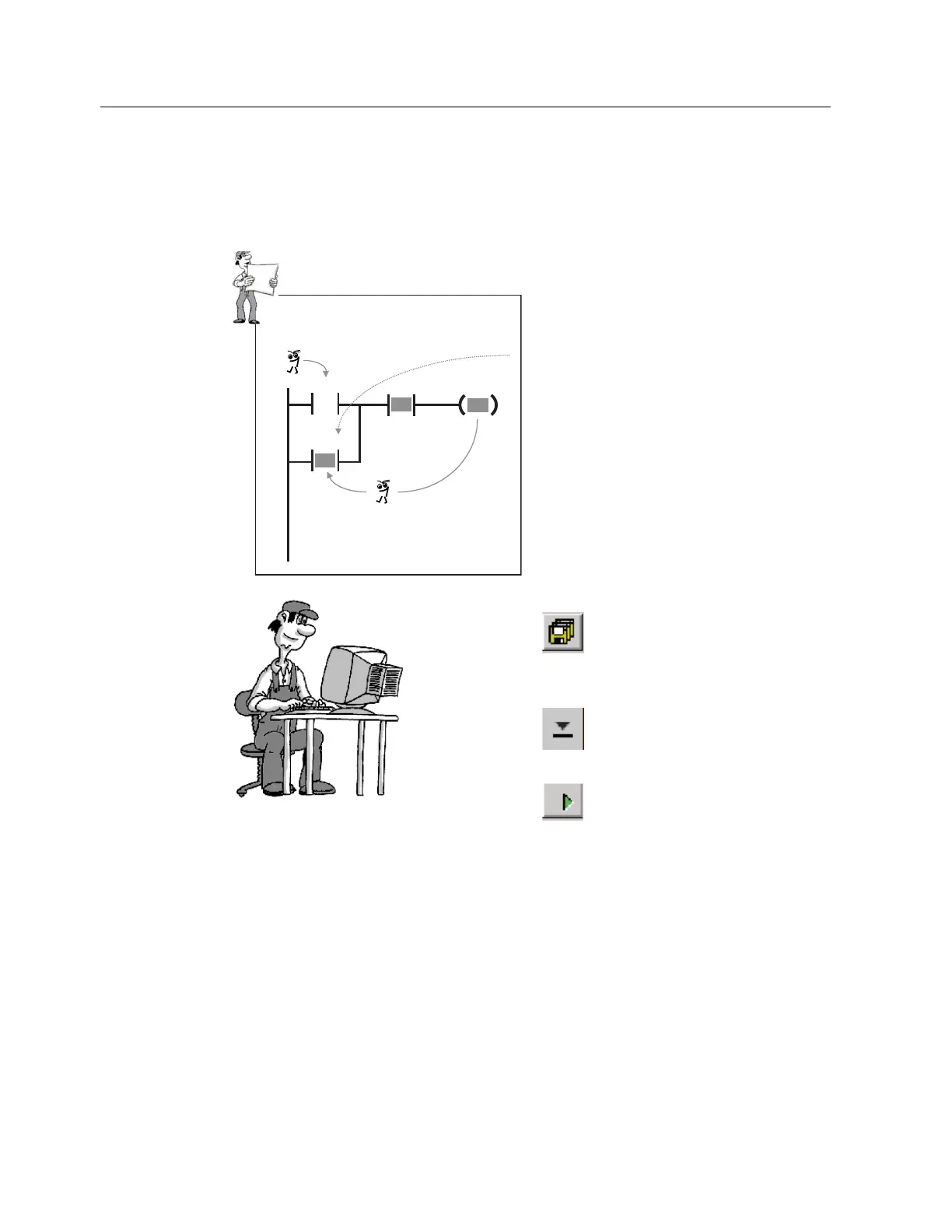
As in the contactor circuit, your LAD network has an output state contact (Q0.0) connected in
parallel with the tripping element (I0.0).
,
4
,
4
1HWZRUN
If, during a scan cycle, output
Q0.0 has been activated by
operation of switch S1 at I0.0,
contact Q0.0 parallel to I0.0 is
closed in the very next cycle
(a few milliseconds later).
This brings about latching.
NC contact I0.1 can terminate
the latch when switch S2 at
I0.1 is operated.
Save your completed program to
hard disk. Then you can load it
again at any time and continue to
edit it . (We will need the program
again for our OFF Delay example.)
Then transfer the program to the
PLC to test the function.
For test purposes, switch the PLC
to the "RUN" mode.
Test your program by operating the two switches on the input simulator connected at I0.0
and I0.1. Observe the lamps on the S7-200 or the LAD output status!
1. Begin by switching ON I0.0.
2. I0.1 must be switched OFF. The LED at I0.0 must light up.
3. Q0.0 will then light up.
4. As soon as I0.1 is switched ON, Q0.0 becomes ="0".

 Loading...


