Getting Started - Advanced
Training Documents, 09/2007, A5E01469795B
63
Appendix A
A
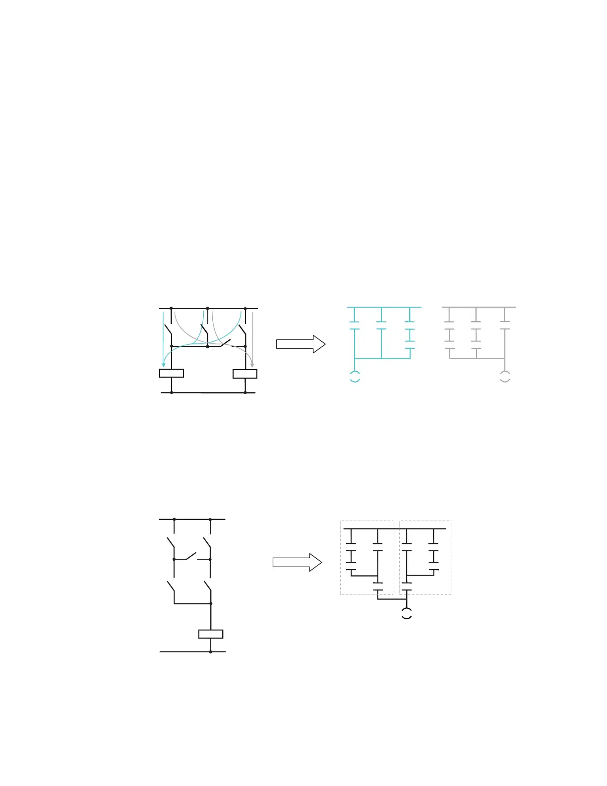
A.1 Bridge Circuit
If you are changing over from contactor technology to PLC technology you will probably
encounter switch combinations that cannot be converted directly into ladder diagram
representation. Included among these is the bridge circuit. Solutions are provided here both
for the simple and the more complex bridge circuit.
Simple bridge circuit
The simple bridge circuit (left) is implemented with two networks. The individual possible
current paths are simply split up. For ease of comparison, we have likewise arranged the
ladder diagram vertically.
D
E
F
G
)
(
)
(
DEF DEF
GGG
Complex bridge circuit
The two possible current paths have been converted again and recombined. On the one
hand, a,c parallel b, on the other b,c parallel a. For ease of comparison, we have arranged
the ladder diagram vertically.
In new projects, avoid using the bridge circuit in the circuit diagram where possible! Think "in
ladder diagram" right from the start.
)
DE
F
G
H
)
D
E
F
G
H
D
E
F

 Loading...


