Pulse Operated Switch
3.7 Solution Description and Test
Getting Started - Advanced
Training Documents, 09/2007, A5E01469795B
29
3.7 Solution Description and Test
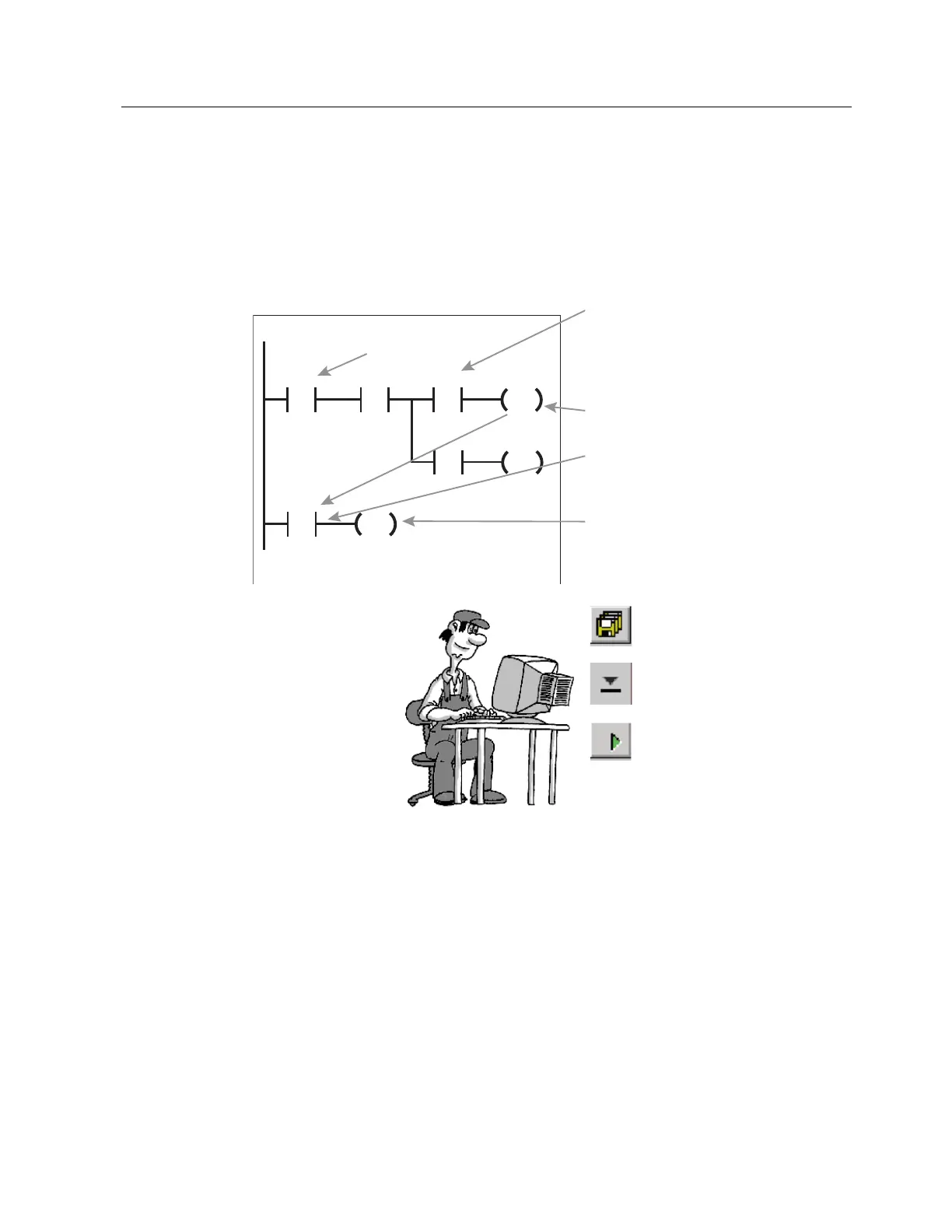
To summarize, the function of our now complete program is explained again below
4
4
0
6
4
0
5
3
,
0
ಯರ
ಯರ
1HWZRUN
1HWZRUN
If I0.0 is operated (P edge detection)
and
Q0.5 is "0" in the current cycle (upper
branch is true on scanning with NC
contact)
then...
Flag the follow-on state of Q0.5 by
setting bit memory M0.0.
M0.0 already has the follow-on state of
Q0.5 here.
Q0.5 is not assigned the new state
until the end of the cycle and so does
not appear as "true" or "1" in the LAD
representation.
Save the completed program to
hard disk.
Transfer the program to the
PLC.
To test, switch the PLC to the
"RUN" mode.
Test your program: Operate the switch
at I0.0 and observe output Q0.5.

 Loading...


