Expert Functions
5.6 Measuring Function
Connection of the SINAMICS S120 to the Technology CPU
164 Product Information, 09/2011, A5E00480378-04
Creating and configuring measuring inputs in S7T Config
To create and configure a measuring input, follow these steps:
1. Switch to the Technology > Axes > Axis_1 > Measuring input folder in the
S7T Config project navigator.
2. Insert the measuring input in the project by clicking "Insert measuring input".
A dialog opens.
3. Click "OK" to confirm the unchanged settings.
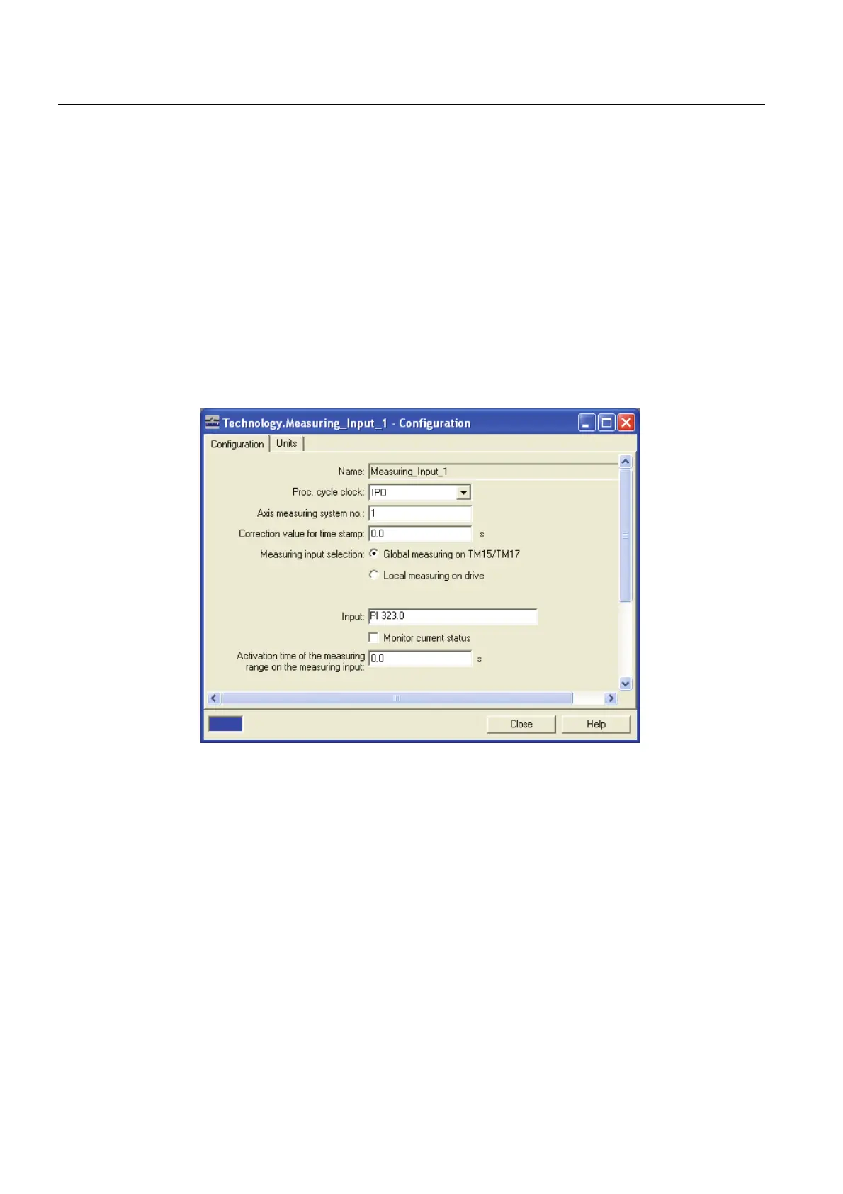
4. To parameterize the measuring input, switch to the
Technology > Axes > Axis_1 > Measuring inputs > Measuring input_1 > Configuration
dialog in the S7T Config project navigator.
The "Configuration" dialog opens.
5. Enter the following input address for this example: PI 323.0.
The address 323 is derived from the offset address of TM17 of 3 bytes and from the
PROFIBUS address of the TM17 module of 320 bytes.
The bit address results from the use of the first DI/O 0 input on the
TM17 terminal module.
Result
This completes the configuring in S7T Config.
As the next step, you will have to create the user program.

 Loading...


