Expert Functions
5.7 Triggering an output cam using the TM17 terminal module
Connection of the SINAMICS S120 to the Technology CPU
Product Information, 09/2011, A5E00480378-04
171
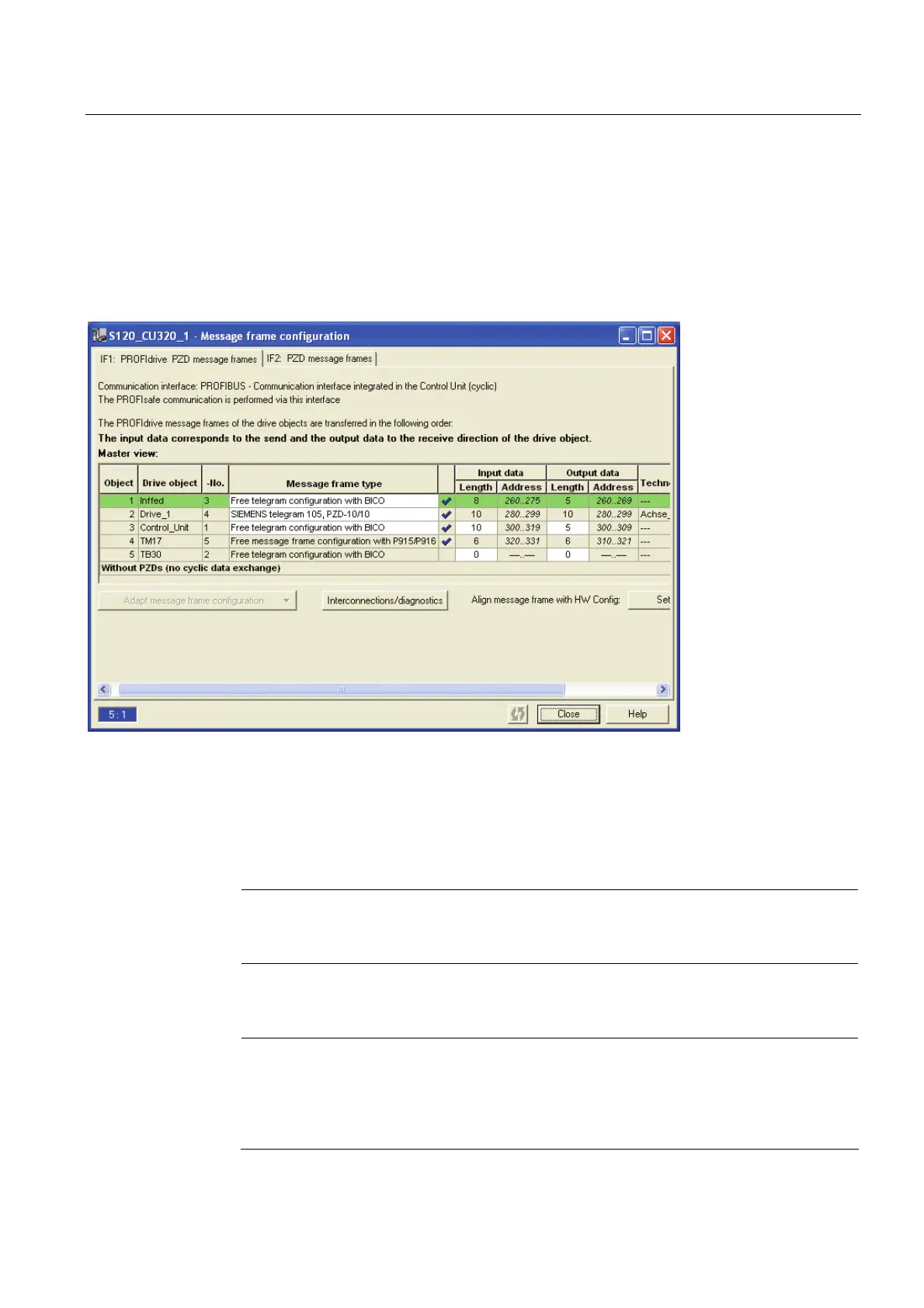
Configuring a message frame
1. For the alignment with the hardware configuration, switch to the
S120_CU320 > Communication > Message frame configuration dialog in the
S7T Config project navigator. The work area shows the newly added
TM17 terminal module.
2. Click "Align message frame with HW Config: Set up addresses".
Following the alignment with HW Config, the TM17 terminal module is assigned the
input/output address via which it can be reached on PROFIBUS DP (DRIVE).
3. For the further processing, note the entry of the TM17 row from the O Address column.
This address, in this example 310..321, is needed for the subsequent address
assignment for the output cam.
The Technology CPU configuration has been changed as a result of inserting the
TM17 terminal module and aligning with HW Config.
Note
Close the message frame configuration after the alignment with HW Config. Otherwise,
it will not be possible to make subsequent changes to the hardware configuration.
4. To transfer the changed configuration to the Technology CPU, open the
HW Config hardware configuration and perform a download.
Note
The alignment in HW Config has caused the message frame to be extended with the
TM17 component. Because this means that the PROFIdrive message frame has become
longer, error messages for the DP configuration can occur. (DP cycle too small).
If necessary, check your setting for PROFIBUS DP.

 Loading...


