Signal Modules of the S7-400
3-7
Automation System S7-400 Configuration and Use
A5E0044271 1-02
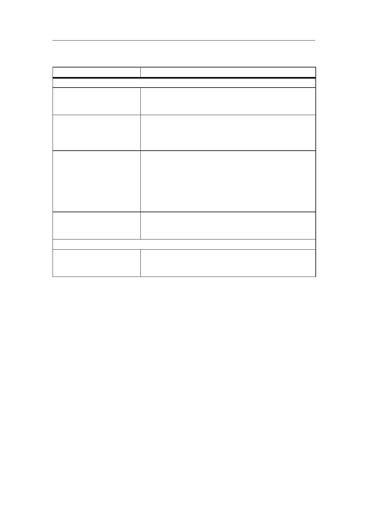
Table 3-1 Performance Characteristics of the Digital Modules, continued
Module Performance characteristics
Digital input module SM 422
DO 16 x 24 V DC / 2 A
6ES7422-1BHxx-0AA0
• 16 outputs, isolated in 2 groups of 8
• Output current 2 A
• Rated load voltage 24 V DC
DO 32 x 24 V DC / 0.5 A
6ES7422-1BLxx-0AA0
• 32 outputs, isolated in one group of 32
• Power is supplied to groups of 8 channels.
• Output current 0.5 A
• Rated load voltage 24 V DC
DO 32 x 24 V DC / 0.5 A
with diagnostics
6ES7422-7BLxx-0AB0
• 32 outputs, fused and isolated in 4 groups of 8
• Output current 0.5 A
• Rated load voltage 24 V DC
• Group error display for internal and external faults
• Programmable diagnostics
• Programmable diagnostic interrupt
• Programmable substitute value output
DO 16 x 120/230 V AC / 2 A
6ES7422-1FHxx-0AA0
• 16 outputs, isolated in 4 groups of 4
• Output current 2 A
• Rated load voltage 120/230 V AC
Relay output module SM 422
DO 16 x 30/230 V UC / Rel. 5 A
6ES7422-1HHxx-0AA0
• 16 outputs, isolated in 8 groups of 2
• Output current 5 A
• Rate load voltage 230 V AC / 125 V DC

 Loading...


