Configuration Variants of the S7-400
6-7
Automation System S7-400 Configuration and Use
A5E0044271 1-02
6.4 S7-400 Assembly in a Rack
Introduction
Regardless of the S7-400 CPU you decide to use, you can equip the module rack
where the CPU is located with up to 16 other modules in addition to the CPU and
the power supply module.
Only Two Slot Rules
You only have to observe two rules when arranging modules in a rack:
• The power supply module must be inserted in slot 1 in all racks. Redundant
power supply modules are inserted in slots 1 and 3.
• The receive IM in the expansion device must always be install at the far right.
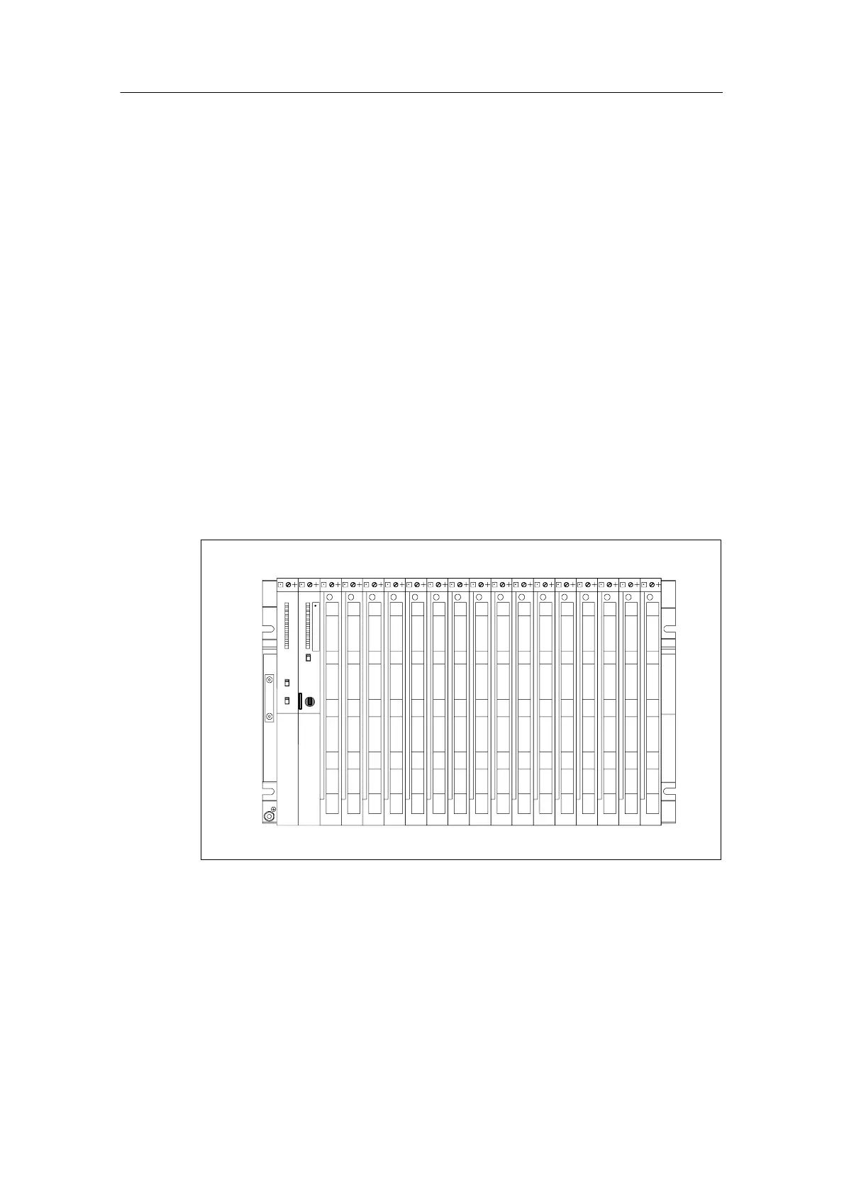
Maximum Assembly with One Rack
Figure 6-3 shows an example of a module configuration in an S7-400 assembly
fully equipped with a power supply module, a CPU and 16 other modules.
PS CPU SMs
Figure 6-3 Rack in the S7-400 system with components
There are racks with 4, 9 or 18 slots for the S7-400.

 Loading...


