Configuration Variants of the S7-400
6-14
Automation System S7-400 Configuration and Use
A5E0044271 1-02
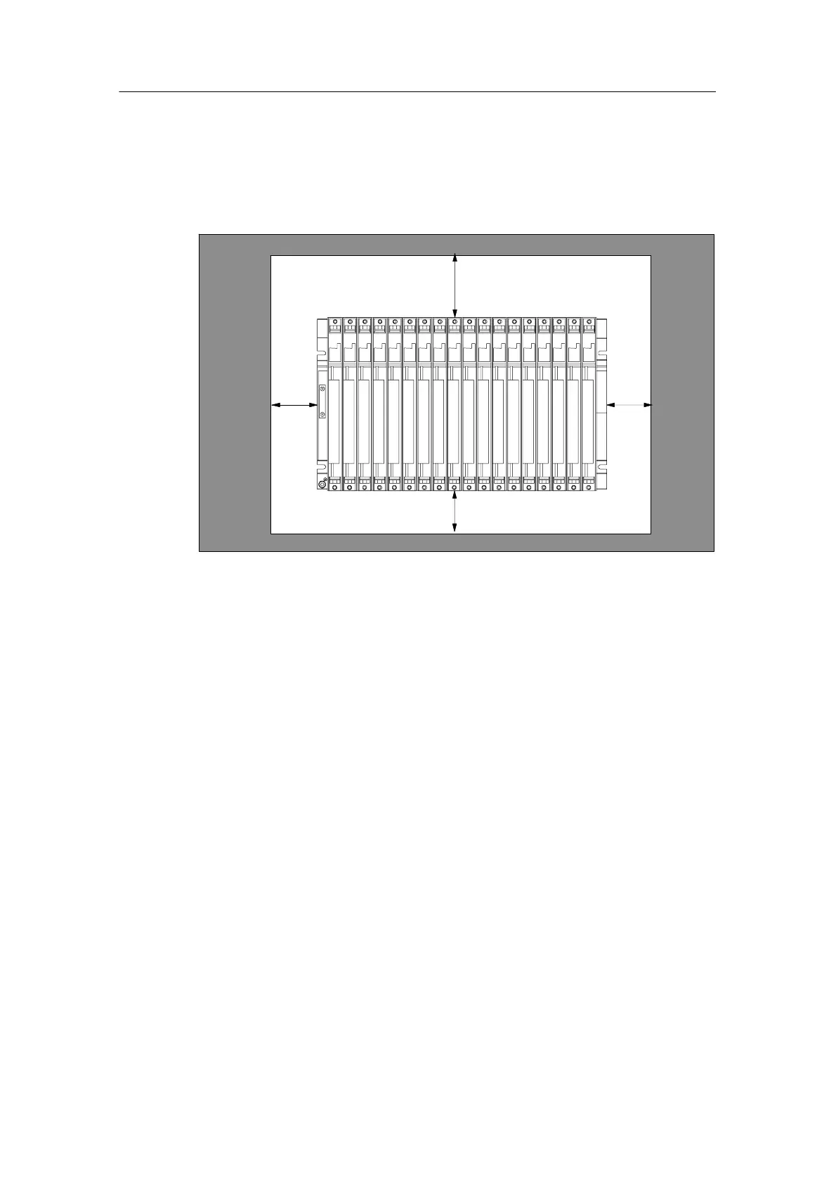
Clearance for a Complete Assembly
Figure 6-6 shows the minimum clearance between adjacent equipment, cabinet
walls, etc., required for a standard S7-400 assembly with a single rack containing
18 slots.
20 mm
20 mm
40 mm
22 mm
1 2 3 4 5 6 7 8 9 101112131415161718
Figure 6-6 Minimum clearance for an S7-400 assembly
Maintaining this clearance ensures the following:
• You ensure heat dissipation for the S7-400 modules.
• You will have enough space to insert and remove S7-400 modules.
• You will have enough space to lay cables.

 Loading...


