Interfaces, Networks and Data Communication for the S7-400
5-8
Automation System S7-400 Configuration and Use
A5E0044271 1-02
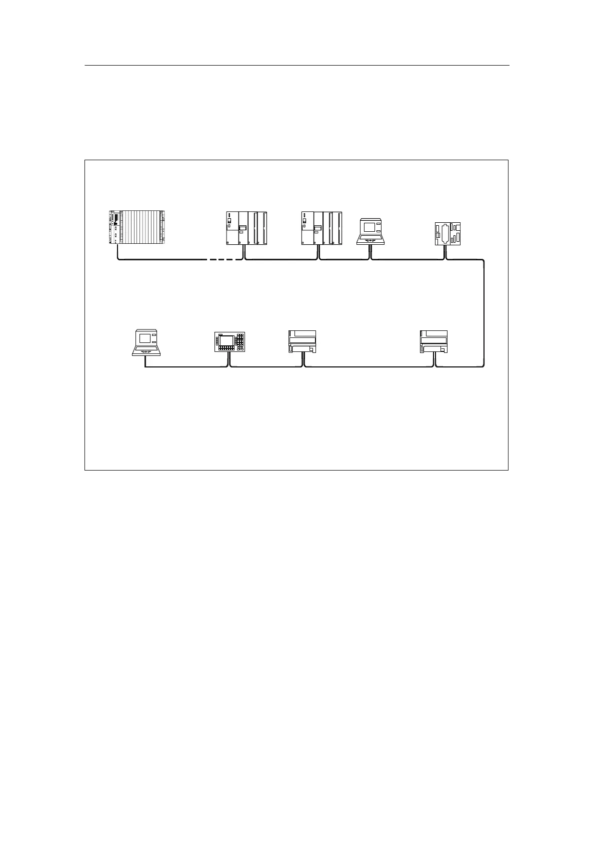
Example of a PROFIBUS DP Configuration
Figure 5-5 shows an example of a PROFIBUS DP configuration with devices from
the SIMATIC S7, SIMATIC S5 and ET 200 series. The S7-400 is the DP master in
this configuration, all other devices are DP slaves.
* only connected by a spur line for commissioning/maintenance work (with PROFIBUS DP address
=0)
0 ... x PROFIBUS DP addresses of the stations
S7-400 with
CPU 414-2-DP
as DP master
ET 200M
0
678
12345
PG*
OP
PG
ET 200M
S5-95U
ET 200BET 200B
Terminal resistor on
Figure 5-3 Example of a PROFIBUS DP network
5.2.3 I/O Interface via PROFINET IO
Introduction
Full communication from the field to the control center is one of the most important
demands in automation engineering today. The technology employed must meet
the following requirements:
• Standardized connection systems
• Uniform network management
• IT access mechanisms
• Comprehensive diagnostic options

 Loading...


