Cycle and Response Times of the S7-400
9.3 Different cycle times
S7-400 Automation System, CPU Specifications
Manual, 10/2006, 6ES7498-8AA04-8BA0
9-7
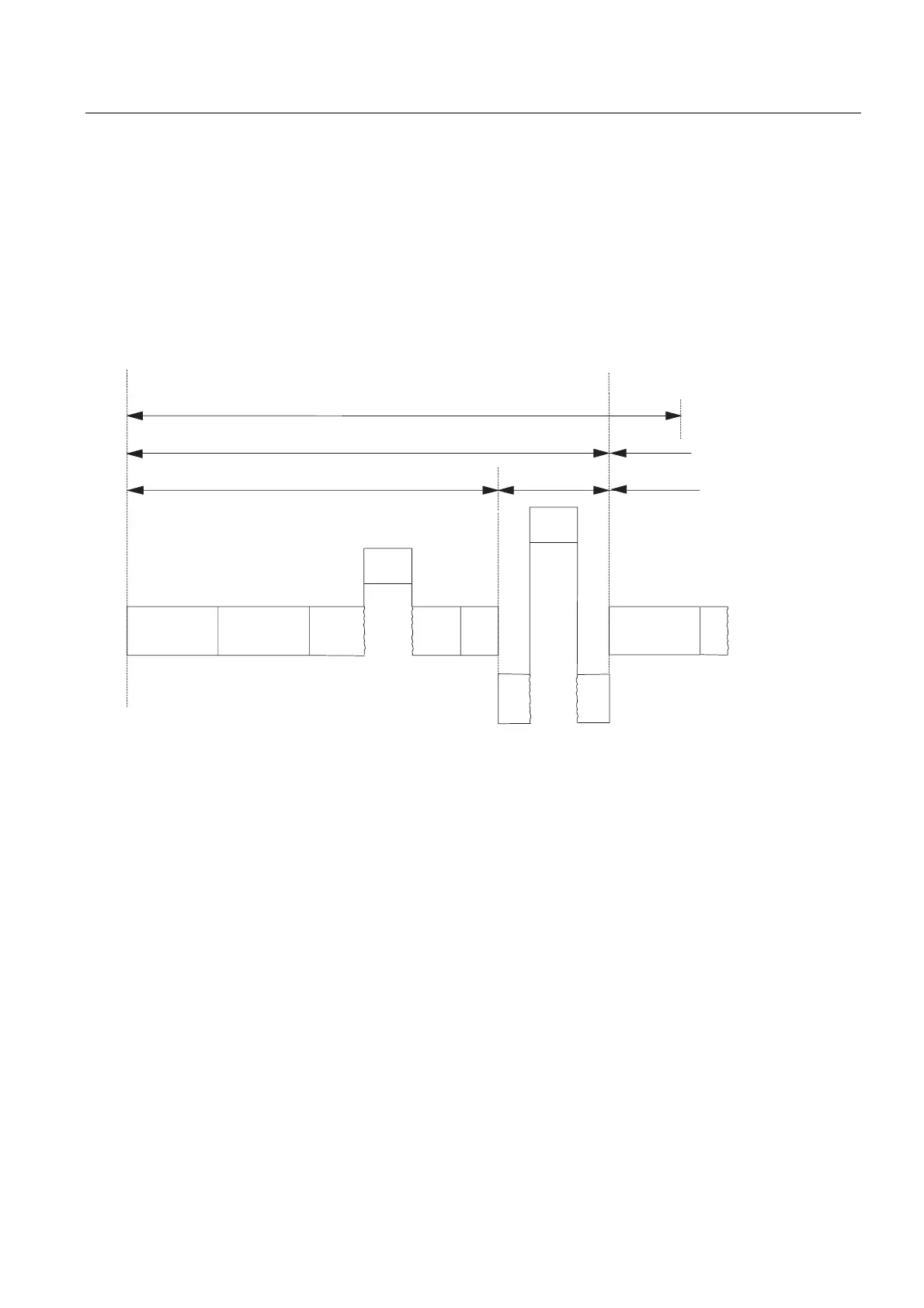
Minimum Cycle Time
You can set a minimum cycle time for a CPU in STEP 7. This is appropriate in the following
cases:
● you want the intervals of time between the start of program scanning of OB1 (free cycle)
to be roughly of the same length.
● updating of the process images would be performed unnecessarily often with too short a
cycle time.
● You want to process a program with the OB 90 in the background.
OB10
OB40
T
T
min
T
max
T
wait
OB1
OB90
OB90
cyc
PCl16
PCl07
PCl01
PK29
(= PK0,29)
SCC
OB1
Current cycle Next cycle
Reserve
Process image
updating
of the outputs
Process image
updating
of the outputs
Process image
updating
of the inputs
Tmin = the adjustable minimum cycle time
Tmax = the adjustable maximum cycle time
Tcyc = the cycle time
Twait = the difference between Tmin and the actual cycle time; in this time,
any interrupts that occur, the background OB and the SCC tasks can be processed.
PCI = priority class
. . .
Figure 9-3 Minimum cycle time
The actual cycle time is the sum of T
cyc
and T
wait
. It is always greater than or equal to T
min.

 Loading...


