Structure of a CPU 41x
2.3 Status and error displays
S7-400 Automation System, CPU Specifications
2-10 Manual, 10/2006, 6ES7498-8AA04-8BA0
Error and Fault Displays and Special Characteristics of the CPU 41x-3PN/DP
The CPUs 41x-3PN/DP furthermore have the LINK LED and the RX/TX LED These LEDs
indicate the current state of the PROFINET interface.
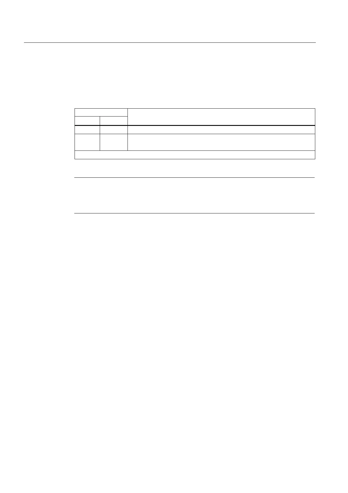
Table 2-7 Possible states of the LINK and RX/TX LEDs
LED
LINK RX/TX
Meaning
H x Connection at PROFINET interface is active
x B
6 Hz
Receive / transmit data at the PROFINET interface.
H = LED is lit; B = LED flashes with the specified frequency; x = LED status is irrelevant
Note
Note
The LINK and RX/TX LEDs are located directly at the sockets of the PROFINET interface.
They are not labeled.
LED MAINT
This LED currently has no function.
Diagnostic Buffer
In STEP 7, you can select "PLC -> Module status" to read the cause of an error from the
diagnostic buffer.