IF 964-DP interface module
11.2 Pin assignment of the IF 964-DP interface module
S7-400 Automation System, CPU Specifications
Manual, 10/2006, 6ES7498-8AA04-8BA0
11-3
11.2 Pin assignment of the IF 964-DP interface module
Connector X1
There is a 9-pin D-sub female connector on the front panel of the module for connecting the
cable. You can see the pin assignment in the following table.
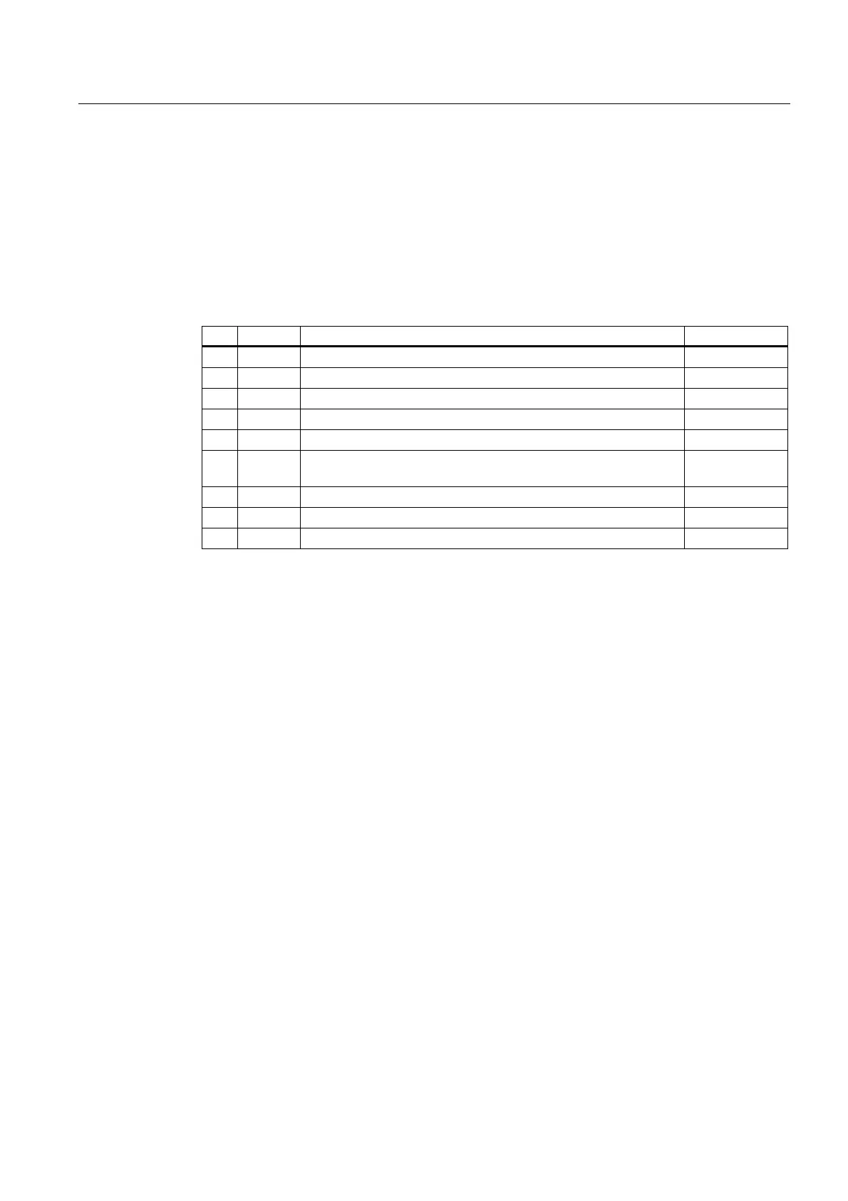
Table 11-1 Female connector IF1 IF 964-DP (9-pin D-sub)
Pin Signal Meaning Direction
1 –
2 M 24 24 V reference potential (6ES7964-2AA01-0AB0) Output
3 LTG_B Line B Input/Output
4 RTSAS request to send (AS) Output
5 M5
ext
Functional ground (isolated) Output
6 P5
ext
+ 5 V (floating), max. 920 mA
(to supply the bus terminator)
Output
7 P 24 V +24 V, max. 150 mA, non-floating Output
8 LTG_A Line A Input
9 –