Cycle and Response Times of the S7-400
9.5 Reaction Time
S7-400 Automation System, CPU Specifications
9-12 Manual, 10/2006, 6ES7498-8AA04-8BA0
DP Cycle Times on the PROFIBUS-DP Network
If you have configured your PROFIBUS-DP network with STEP 7, then STEP 7 will calculate
the typical DP cycle time that must be expected. You can then have the DP cycle time of
your configuration displayed for the bus parameters on the programming device.
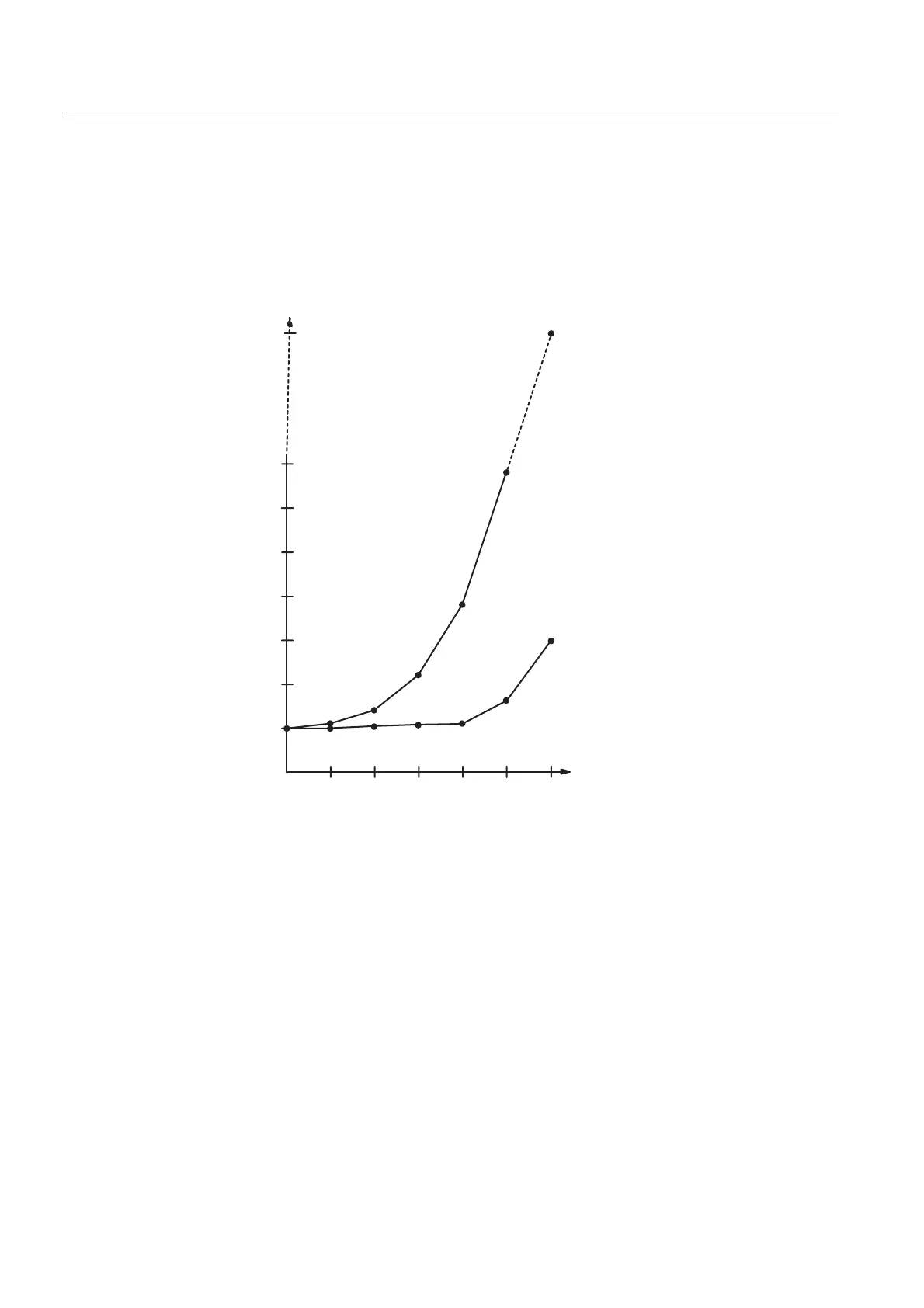
The following figure will provide you with an overview of the DP cycle time. We assume in
this example that each DP slave has 4 bytes of data on average.
6 ms
4 ms
2 ms
1 2 4 8 16 32
1 ms
3 ms
5 ms
7 ms
64
17 ms
Bus
transit
time
Baud Rate: 1,5 Mbps
Baud Rate: 12 Mbps
Number of DP slaves
Min. slave-
interval
Figure 9-7 DP Cycle Times on the PROFIBUS-DP Network
With multi-master operation on a PROFIBUS-DP network, you must make allowances for the
DP cycle time at each master. That is, you will have to calculate the times for each master
separately and then add up the results.

 Loading...


