PROFIBUS DP
5.1 CPU 41x-3 PN/DP as DP master / DP slave
S7-400 Automation System, CPU Specifications
5-24 Manual, 10/2006, 6ES7498-8AA04-8BA0
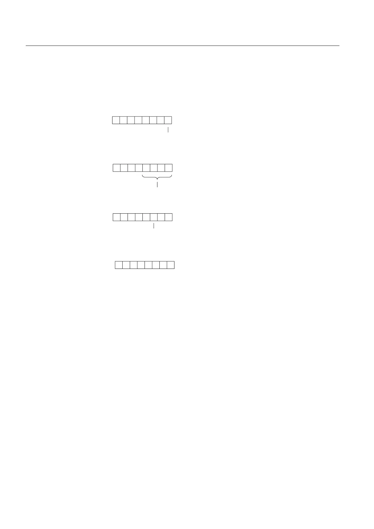
Bytes x +4 to x +7 for Diagnostic Interrupts
The following figure illustrates the structure and contents of bytes x +4 to x +7 for the
diagnostic interrupt. The data in these bytes correspond to the contents of data record 0 of
diagnostic data in STEP 7 (in this case, not all bits are used).
Byte x +4
70
Byte x +5
Byte x +6
0
1
00 0 0
1
74 0
02
3
7
02
7
00
000001
0000000
Byte x +7
70
00000000
Bit no.
Bit no.
Bit no.
Bit no.
0: Module OK.
1: Module error
Identifier for address area of the
Intermediate memory (constant)
0: RUND mode
1: STOP mode
Figure 5-6 Bytes x +4 to x +7 for diagnostic and hardware interrupts
Interrupts with the S7 DP Master
In the CPU 41x as a DP slave you can trigger a process interrupt in the DP master from the
user program. You can trigger an OB40 in the user program of the DP master by calling
SFC7 "DP_PRAL". Using SFC7, you can forward interrupt information in a double word to
the DP master and evaluate it in OB40 in the OB40_POINT_ADDR variable. You can
program the interrupt information to suit your purposes. You will find a detailed description of
SFC7 "DP_PRAL" in the
System Software for S7-300/400, System and Standard Functions
reference manual.
 Loading...


