3 FM-STEPDRIVE specifications 02.05
© Siemens AG 1998 All Rights Reserved
3-4 FM-STEPDRIVE/SIMOSTEP (FB)
Signal interface
Note
Alls signals are PELV (protected extra low voltage) signals as defined in
VDE 0160.
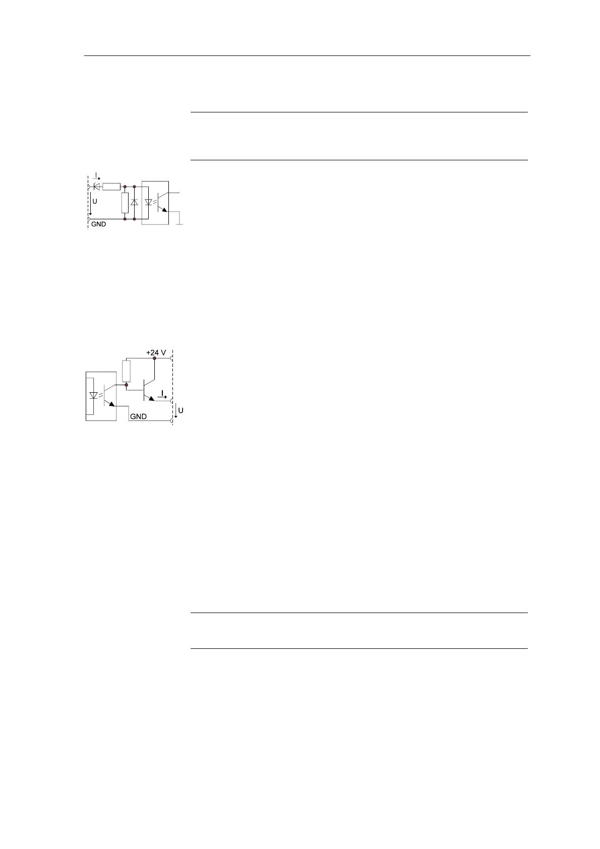
Signal interface input
GATE_N (enable/disable the clock signal). ENABLE_N (enables the
amplifier). For a signal description, see chapter 4.
24 V standard PLC optocoupler input:
U
high, min
= 15 V I
high, min
= 2 mA
U
high, max
= 30 V I
high, max
= 15 mA
U
low, max
= 5 V I
low, max
= 0.2 mA Input open corresponds
U
low, min
= -3 V I
low, min
= -15 mA to low signal.
Max. transient overvoltage 35 V/500 ms
Signal interface outputs
READY2 (readiness), ZERO (ring counter zero signal), MSTILL (Motor
standstill). For a signal description, see chapter 4.
24 V standard PLC output READY2 (overload and short-circuit protected):
U
high
24 V supply voltage
Voltage drop 3 V max. at 70 mA
Output current 70 mA
Sustained short-circuit current 0.6 A max.
Peak current 5 A max. for 50 ms
U
low
Output open
Leakage current 150 µA max.
24 V standard PLC output ZERO (overload and short-circuit protected):
Voltage drop 3 V max. at 30 mA
Output current 30 mA max.
other data as for output READY2
External 24 V supply for signal interface
Note
The 24 V voltage supply must meet the specifications of DIN 19240.
Voltage range 18.5 V to 30.2 V DC
Ripple 3.6 Vpp
Input current 1.5 A max.
Transient overvoltage 35 V / 500 ms max.