6 Wiring 02.05
© Siemens AG 1998 All Rights Reserved
6-2 FM-STEPDRIVE/SIMOSTEP (FB)
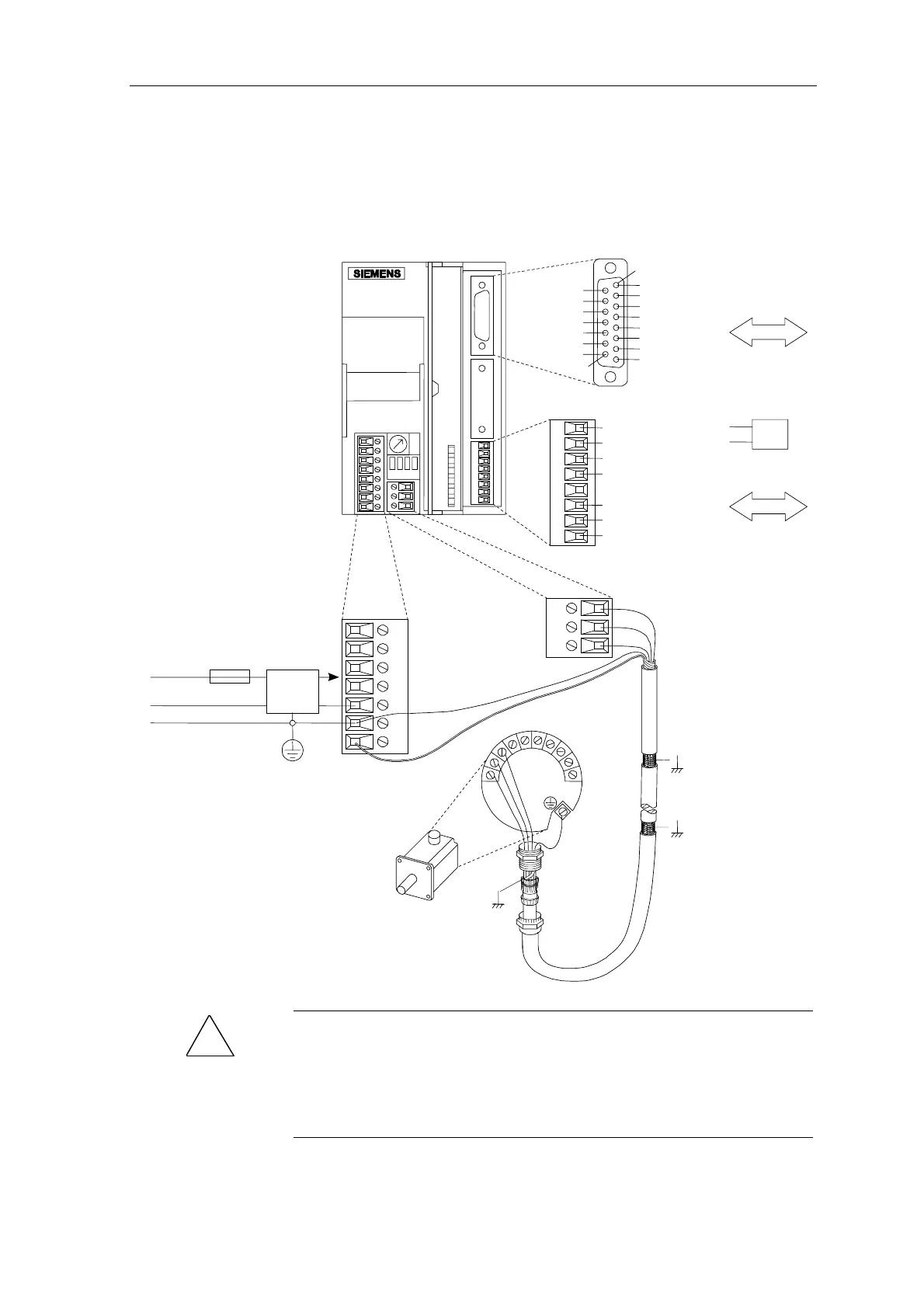
6.1 FM-STEPDRIVE and SIMOSTEP wiring
Wire the FM-STEPDRIVE power controller and the SIMOSTEP series
motor in accordance with figure 6-1.
Motor connection
Mains/intermediate
circuit connection
Pulse interface
Control unit
Control unit
Supply
SIMOSTEP motor
115 VAC
or
230 VAC
N
PE
Fuse
DC
+
DC
-
115
230
N
PE
MS
U
U
V
V
W
W
(W)3
(V) 2
(U) 1
4
5
6
7
8
9
0
Signal interface
FM-STEPDRIVE
PULSE_N
DIR_N
ENABLE_N
PWM_N
GND
GND
READY1_N
PULSE
DIR
ENABLE
PWM
GND
GND
Not used
GND
1
15
24 V
L
Shield
connection
Strain relief spring
Shield
connection
Mounting plate
Shield connection
Motor cable gland
Mains
filter
READY2
ZERO
MSTILL
GATE_N
M (24V GND)
L+ (24 V)
ENABLE_N
PE
PE
Schild connection
as short as possible
Figure 6-1 FM-STEPDRIVE and SIMOSTEP wiring
!
Danger
The supply voltage must be disconnected whenever wiring work is carried
out. When the supply voltage is connected, high voltages are present on
the mains, intermediate circuit and motor connections. Never touch these
connections when the unit is switched on, since this constitutes a danger
of death or severe injuries.