6 Wiring 02.05
© Siemens AG 1998 All Rights Reserved
6-4 FM-STEPDRIVE/SIMOSTEP (FB)
6.2 Wiring example for FM-353 and FM-NC/FM357
Wiring with FM-353
positioning module
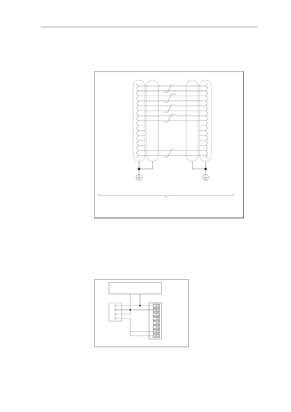
The following figure illustrates the wiring layout for connecting the pulse
interface to the FM-353 positioning module:
Pulse interface cable for FM-353
Order no.: 6FX2002-3AC02-1xx0
(xx is the length in m),
see NC60.1 or NCZ catalogues
PULSE_N PULSE_N
PULSE
FM-353 FM-STEPDRIVE
PULSE
11bk
99br
22rd
10 10or
33ye
11 11gn
44bu
12 12vio
55
13 13
66
14 14
77
88gy
15 15wh
DIR DIR
DIR_N DIR_N
ENABLE ENABLE
ENABLE_N ENABLE_N
PWM/BOOST PWM
PWM_N/BOOST_N PWM_N
M GND
GND
GND
GND
M
M
M
Not used Not used
M GND
READY_N
Sub-D Sub-DCable 8 x 2 x 0.18
15 pin female 15 pin femaleshielded
READY1_N
Figure 6-2 Connecting the FM-STEPDRIVE power controller to FM-353
The FM-353 positioning module can evaluate the READY2 or ZERO
output signals (refer to manual on SIMATIC S7 positioning module FM
353, order no. 6ES7 353-1AH00-7AG0). Depending on the operating
mode used on the FM-353, the RM-P input of the 20-pin front panel
connector of the FM-353 must be wired to the ZERO output or to the
READY2 output of the signal interface on the FM-STEPDRIVE power
controller. The following figure illustrates the wiring layout of the signal
interface with common voltage supply:
FM-STEPDRIVEFM-353
Common 24 V
supply
Signal interface
19
20
10
9
X1
L+
L+M
M
RM_N
RM_P
READY2
ZERO
MSTILL
GATE_N
M (24 V GND)
L+ (24 V)
ENABLE_N
Figure 6-3 Signal interface wiring layout for connection to FM-353