02.05 6 Wiring
© Siemens AG 1998 All Rights Reserved
FM-STEPDRIVE/SIMOSTEP (FB)
6-5
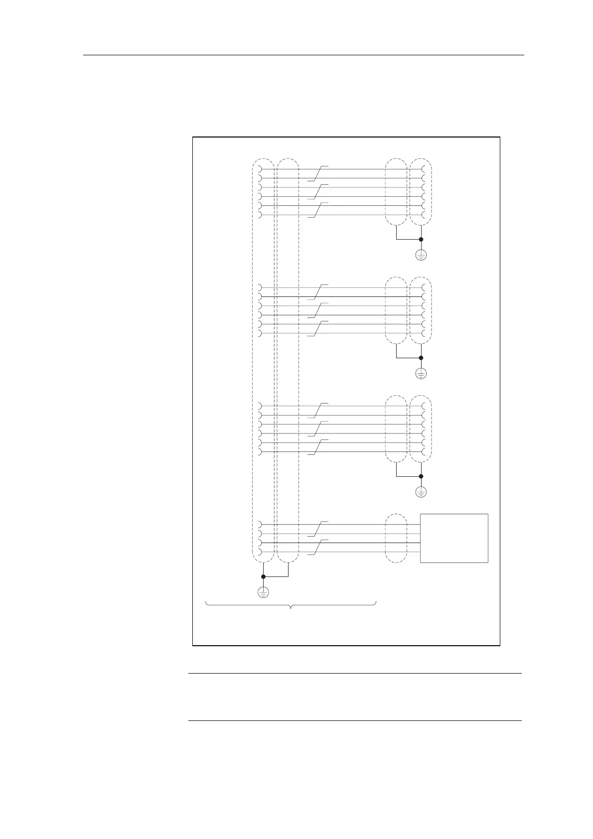
Multi-axis wiring
with FM-NC/FM357
controller
The following figure illustrates the wiring layout for connecting three FM-
STEPDRIVE power controllers and one drive with a ±10V interface to the
FM-NC/FM357 controller:
PULS1_N
PULS2_N
PULS3_N
RF4.2
PULSE_N
PULSE_N
PULSE_N
PULS1
PULS2
PULS3
RF4.1
FM-NC/FM357 FM-STEPDRIVE
FM-STEPDRIVE
FM-STEPDRIVE
PULSE
PULSE
PULSE
5
40
9
17
1
1
1
black
white/grey
white/black
white/yellow
38
7
42
50
9
9
9
brown
brown/black
white/brown
white/green
6
41
10
4
2
2
2
red
blue
brown/red
white/blue
39
8
43
37
10
10
10
orange
violet
brown/orange
white/violet
18
20
26
3
3
3
yellow
grey
white/red
19
21
27
11
11
11
green
white
white/orange
DIR1
DIR2
DIR3
BS4
DIR
DIR
DIR
DIR1_N
DIR2_N
DIR3_N
SW4
DIR_N
DIR_N
DIR_N
ENABLE1
ENABLE2
ENABLE3
ENABLE
ENABLE
ENABLE
ENABLE1_N
ENABLE2_N
ENABLE3_N
ENABLE_N
ENABLE_N
ENABLE_N
Sub-D
Sub-D
Sub-D
Sub-D
50 pin female
15 pin female
15 pin female
15 pin female
Drive with
±10 V interface
Cable 12 x 2 x 0.14
shielded
Pulse interface cable for FM-NC/FM357
Order no.: 6FX2002-3AD02-1xx0 (xx is the length in m),
see NC60.1 or NCZ catalogues
Figure 6-4 Connecting three FM-STEPDRIVEs and one drive with ±10 V interface to the
FM-NC/FM357 controller
Note
24 V must be applied on the GATE_N input of the FM-STEPDRIVE signal
interface for pulse enabling.