Fail-Safe Electronic Modules
8.1 8 /16 F-DI DC24V PROFIsafe Digital Electronic Module
ET 200pro Distributed I/O System - Fail-Safe Modules
Operating Instructions, 05/2007, A5E00394073-02
71
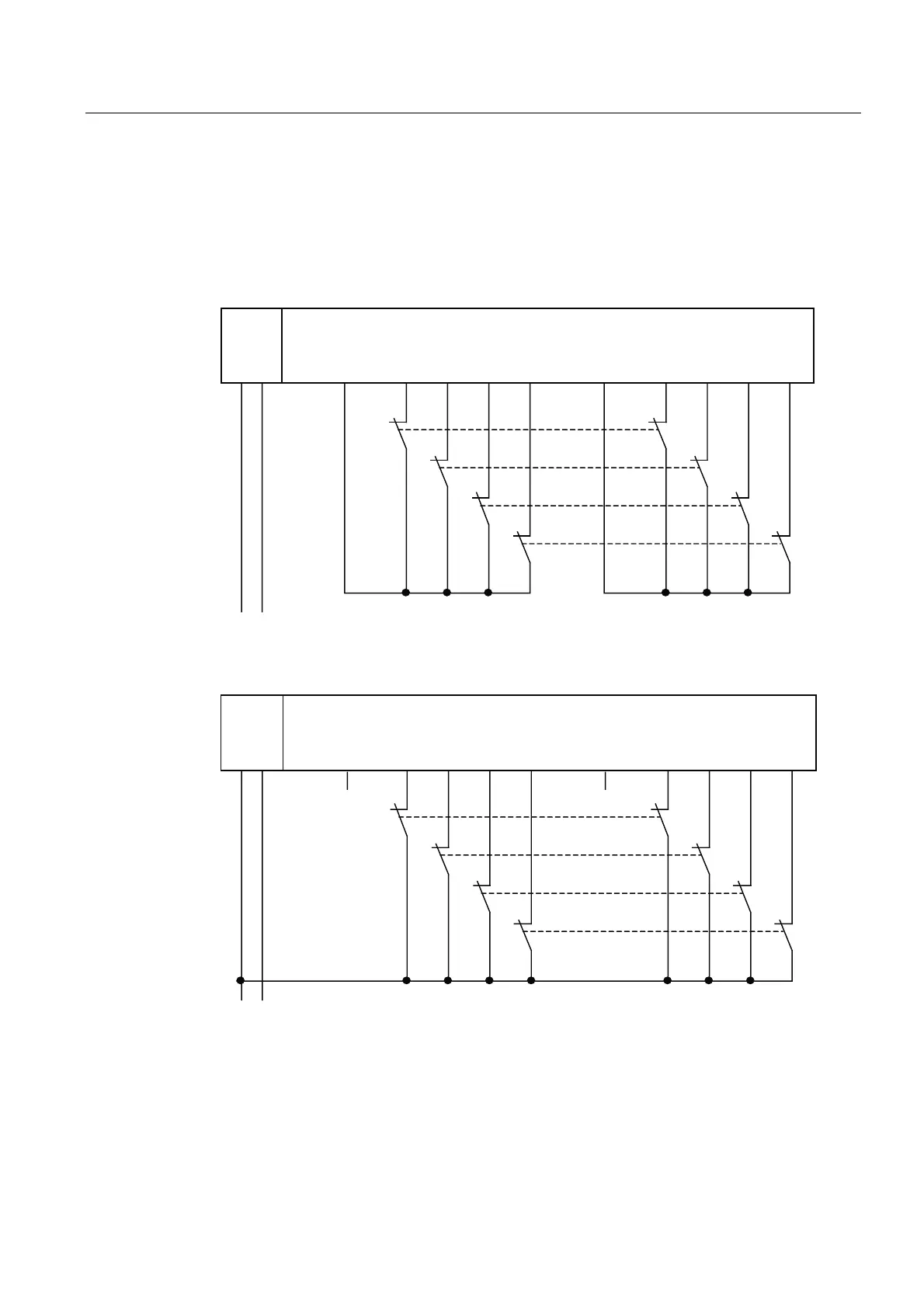
Wiring Diagram for Use Case 2.2 – Connecting One Two-Channel Sensor Via Two Channels
One two-channel sensor is connected via two channels to two inputs of the F-module for
each process signal (1oo2 evaluation).
The wiring is carried out at the appropriate connection module.
The figures below illustrate an example wiring diagram for channel groups 1 and 2.
)',
)',)'2
/
0 ', ', ', ', ', ', ', ', 9V 9V
/ 0
6
6
6
6
/
6HQVRUFRQWDFWVDUHPHFKDQLFDOO\FRXSOHG
Figure 8-7 Wiring Diagram for F-DI Modules - One Two-Channel Sensor Connected, Internal
Sensor Supply
8/16 F-DI
4/8 F-DI/4 F-DO
1L+ M DI0 DI1 DI2 DI3 DI4 DI5 DI6 DI7 Vs1 Vs2
L+ M
S0
S1
S2
S3
1L+
Sensor contacts are mechanically coupled.
Figure 8-8 Wiring Diagram for F-DI Modules - One Two-Channel Sensor Connected Via Two
Channels, External Sensor Supply