Fail-Safe Electronic Modules
8.1 8 /16 F-DI DC24V PROFIsafe Digital Electronic Module
ET 200pro Distributed I/O System - Fail-Safe Modules
72 Operating Instructions, 05/2007, A5E00394073-02
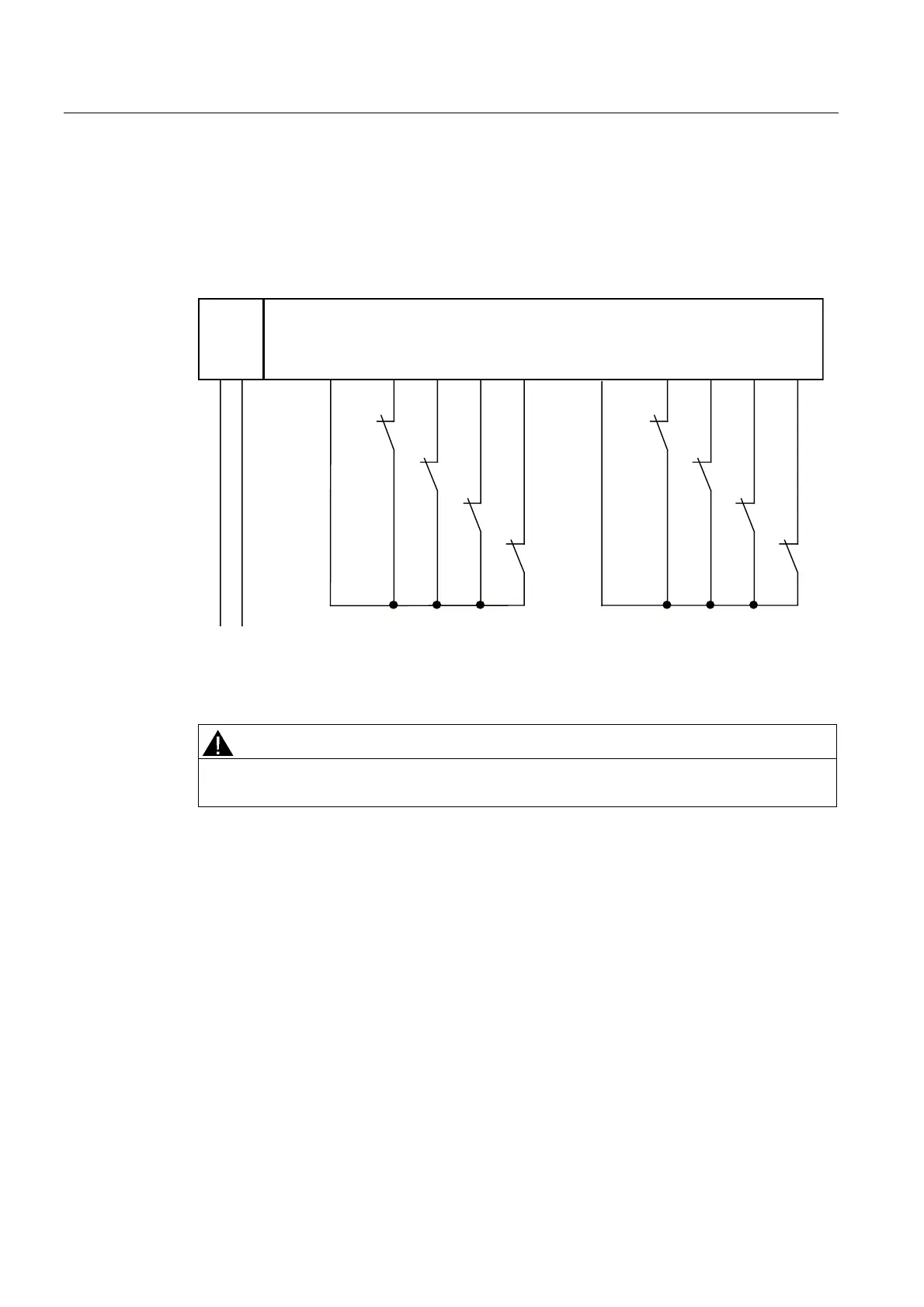
Wiring Diagram for Use Case 2.2 – Connecting Two One-Channel Sensors Via Two Channels
Two single-channel sensors are connected via two channels to two inputs of the F-module
for each process signal (1oo2 evaluation). The sensors can also be supplied via an external
sensor supply.
The figure below illustrates an example wiring diagram for channel groups 1 and 2.
1L+ M DI0 DI1 DI2 DI3 DI4 DI5 DI6 DI7 Vs1 Vs2
L+ M
S0
S1
S2
S3
8/16 F-DI
4/8 F-DI/4 F-DO
1L+
Figure 8-9 Wiring Diagram for F-DI Modules - Two One-Channel Sensors Connected Via Two
Channels, Internal Sensor Supply
WARNING
In order to achieve SIL3/Category 3 with this wiring, you must install a suitably qualified
sensor, for example, in accordance with IEC 60947.
Assignable Parameters for Use Case 2.2
Set the "Evaluation of the sensors" parameter to "1oo2 evaluation" and the "Type of sensor
interconnection" parameter to "2-channel equivalent" for the relevant input. Disable the
"Short-circuit test" parameter.