Fail-Safe Electronic Modules
8.1 8 /16 F-DI DC24V PROFIsafe Digital Electronic Module
ET 200pro Distributed I/O System - Fail-Safe Modules
Operating Instructions, 05/2007, A5E00394073-02
85
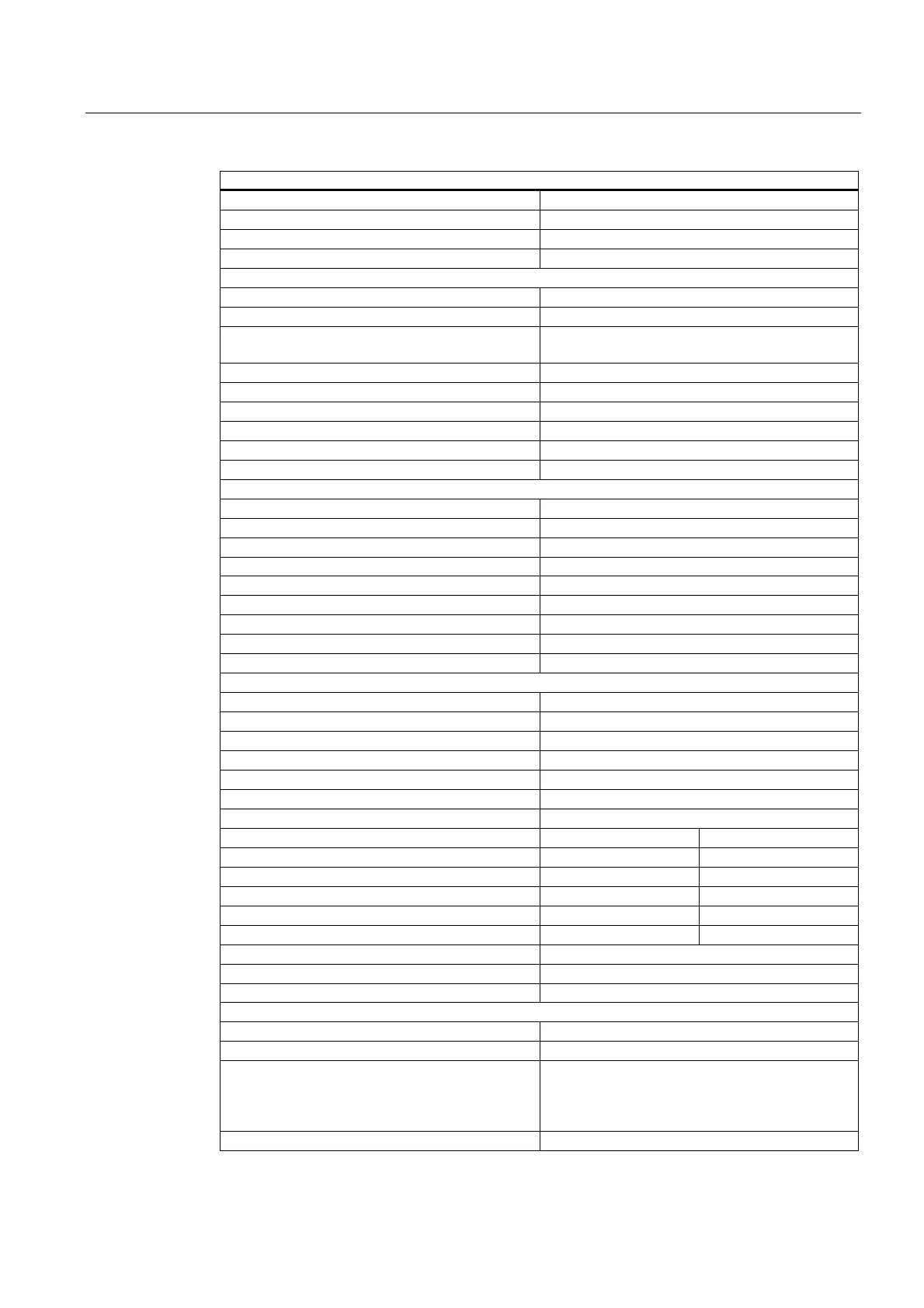
Technical Specifications
Current consumption
• From backplane bus
Typ. 20 mA
• From load voltage L+ (without sensor)
Typ. 120 mA
Power loss of module Typ. 4.5 W
Status, Interrupts, Diagnostics
Status displays
• Inputs
Two-color red/green LED per channel
• Sensor supply
LED VsF and display via channel LEDs of
channel groups
Diagnostic functions
Interrupts
• Diagnostic interrupt
Channel LED red
• Group fault display
Red LED (SF)
• Diagnostic information can be read out
Possible
• I&M functionality *
See "ET 200pro Distributed I/O" Manual
Sensor Supply Outputs
Number of outputs 4
Output voltage
• Loaded
Min. L+ (-1.5 V)
Output current
• Rated value
200 mA
• Permissible range
0 mA to 200 mA
Permissible aggregate current of outputs 800 mA
Short-circuit protection Yes, electronic
• Operating value
0.7 A to 2.1 A
Data for Selecting a Sensor **
Input voltage
• Rated value
24 V DC
• "1" signal
15 V to 30 V
• "0" signal
-30 V to 5 V
Input current
• "1" signal
Typ. 3.7 mA
Input delay Assignable (for all inputs together)
• For "0" after "1"
Typ. 0.5 ms (0.3 ms to 0.7 ms)
Typ. 3 ms (2.6 ms to 3.4 ms)
Typ. 15 ms (13 ms to 17 ms)
• For "1" after "0"
Typ. 0.5 ms (0.3 ms to 0.7 ms)
Typ. 3 ms (2.6 ms to 3.4 ms)
Typ. 15 ms (13 ms to 17 ms)
Input characteristic In accordance with IEC 61131-2, Type 1
Connection of 2-wire BERO Not possible
• Permissible quiescent current
Max. 0.6 mA
Time, Frequency
Internal preprocessing times See
"Response Times"
Acknowledgment time in safety mode
• Short-circuit test enabled
With input delay of 0.5 ms:
With input delay of 3 ms:
With input delay of 15 ms:
Min. 4 ms / max. 7 ms
Min. 4 ms / max. 12 ms
Min. 4 ms / max. 9 ms
• Short-circuit test disabled
Min. 4 ms / max. 6 ms