611V3usa.PPT
Sheet 3/3 - 8/10/98
1) Tighten DC Link Screws (Torx T-20) 1.8Nm (16in-lbs)
2) Commutating Reactor should be located as close as
possible to the I/R Module.
3) Fuses - Not supplied with system:
Module Rated Input Suggested Suggested
Rating Current Siemens Fuse Fuseholder
5 KW 12.5 A 3NA3805 3NH4030
10 KW 24 A 3NA3810 3NH4030
28 KW 65 A 3NA3824 3NH4030
16 KW 27 A 3NA3814 3NH4030
36 KW 60.5 A 3NA3824 3NH4030
55 KW 92.5 A 3NA3832 3NH4030
80 KW 134 A 3NA3136 3NH4230
120 KW 202 A 3NA3144 3NH4230
4) Voltage measurements should be balanced when
checked; Line to Line and Line to Ground .
5) Alternate Fuse location. [ Note that different fuse ratings
may be required at this location vs the fuses in note 3) ]
6) Transformer must have an Impedance Voltage rating of >1% , < 3% .
NOTE: Applies to: 16, 36, 55, 80 & 120 KW I/R Modules Only
In applications where a Contactor, Disconnect, etc., might be
opened while the Drive’s I/R Module is in the DC Bus Regulating
Mode, the Infeed/Regeneration Module must be disabled
(terminal 48 or 63) => 10ms prior to the opening of the line
contacts. If this instruction is not adhered to, I/R module damage
could result. In cases of “brown-out” or loss of Power Company
power, a complete circuit remains to absorb the regenerative
energy and failures should not occur.
7)
8) The I/R Module input voltage must be derived from a TN-C, (Wye
connection with Neutral Ground,) system. If configuration and
voltage specifications are according to requirements, a matching
transformer is not required. See Planning Guide for Details.
8.1) If line configuration is not TN-C, an isolation transformer with
neutral ground connection is required. See Planning Guide for
proper sizing and configuration details.
8.2) If line configuration is TN-C, an auto transformer can be used
to provide correct input voltage.
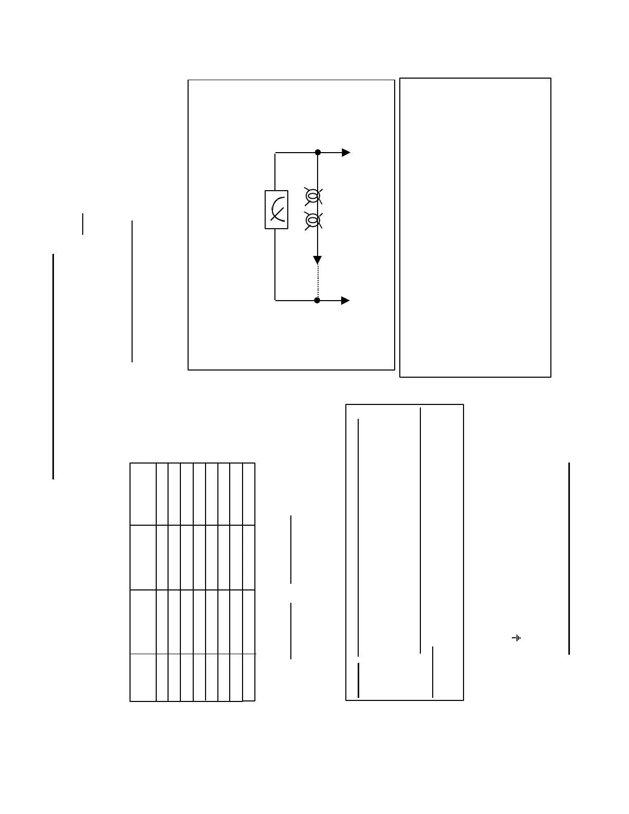
2 @ 60W x 120VAC
Voltmeter
Machine
Ground
U1, V1 or W1
on I/R - U/E
Module
To verify TN-C line neutral connection is present, connect
meter as shown and note reading. When lightbulb assembly
is connected, reading should not change and bulbs should
glow normally. Note: Terminal 48 must be disabled
611-A V3 Power & Grounding Notes
Section A Power & Grounding
9) Terminals L1-L2 are only available for the 80 and 120KW I/R
modules only. F1-F2 fuses should be greater than or equal to 4A
depending upon the maximum cable cross-section. If the input
voltage fails or F1-F2 fuses blow, the I/R module pulses are
disabled and the internal line contactor drops out. The I/R module
will display the line fault LED, and the ready relay and the internal
line contactor contacts will drop out. Terminal 48 must be de-
energized and can be re-energized again after >1 sec. or if the
power is turned off and on again. In this case, the jumper between
terminals 9 & 48 must be removed and a switch inserted. The
switch is not required if the system is powered off and on again
using the main supply circuit breaker.
A* Shield connections must be made on both sides of
power cables using the highest possible area.
B* Each Power Section must have separate leads from the
terminal “ “ to the machine ground bus.
 Loading...


