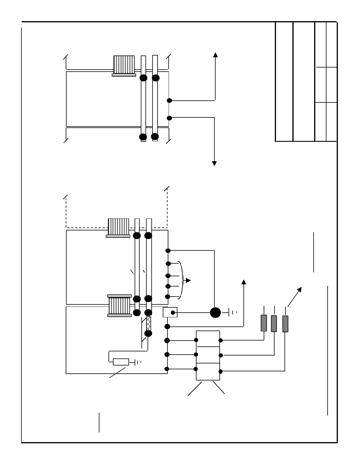
611-A “I / R” Mod.
U1 V1 W1 X131 PE1
Commutation
Reactor
6SN1111-.....
(not required
for 10 / 25 KW)
400 VAC + / -10 %, 50/60 Hz., 3 Phase.
480 VAC + 6% / - 10%.
Lines should be balanced referenced to Ground.
(6SN1145- 1B . . . )
Servo, Main Spindle
or Induction Motor
Module
( 6SN1118-.....
6SN1121-.....
6SN1122-..... )
U2 V2 W2 PE2 PE1
Motor Power
Connections
Earth Ground
Star Point
Size Fuses to I / R Module requirements
(see “Project Planning” Tech. Data ) Note: If a Line Contactor or Disconnect is used,
it must not open until = / > 40ms after
Term. 63 or 48 is opened !
Ribbon
Cable
Connections
to / from next
Module ( if any )
611A System: To CNC Chassis ( O Volt Reference)
611D System: To Earth Ground Star Point
Monitoring Module
( if used )
( 6SN1112-.....)
Preceding
Module
Following
Module
PE1 X131
To Earth Ground
Star Point
To CNC Ground
Star Point
Note: Mount Reactor
as close to “I / R”
Module as is
practical.
DC Link
P600
M600
R
See Note 1.
Note 1.: Connect
M600 link to resistor
“R”.
This connection
provides a reference
through 100 k ohms
for M600 to earth
ground. Do not
connect M600 direct
to earth ground!
Next Module
( if any )
Siemens Energy & Automation
Machine Industry Business
Drawing for ; 611-A , General Wiring for
Power, Grounding and Module
Interconnection
Date Revision Drawn by
8/13/98 Rev. A-5 de/sc/dk
Page 1 / 4
Section C - Non CE Configuration shown
1U2 1V2 1W2
1U1 1V1 1W1
 Loading...


