3
Siemens Energy & Automation
Machine Industry Business
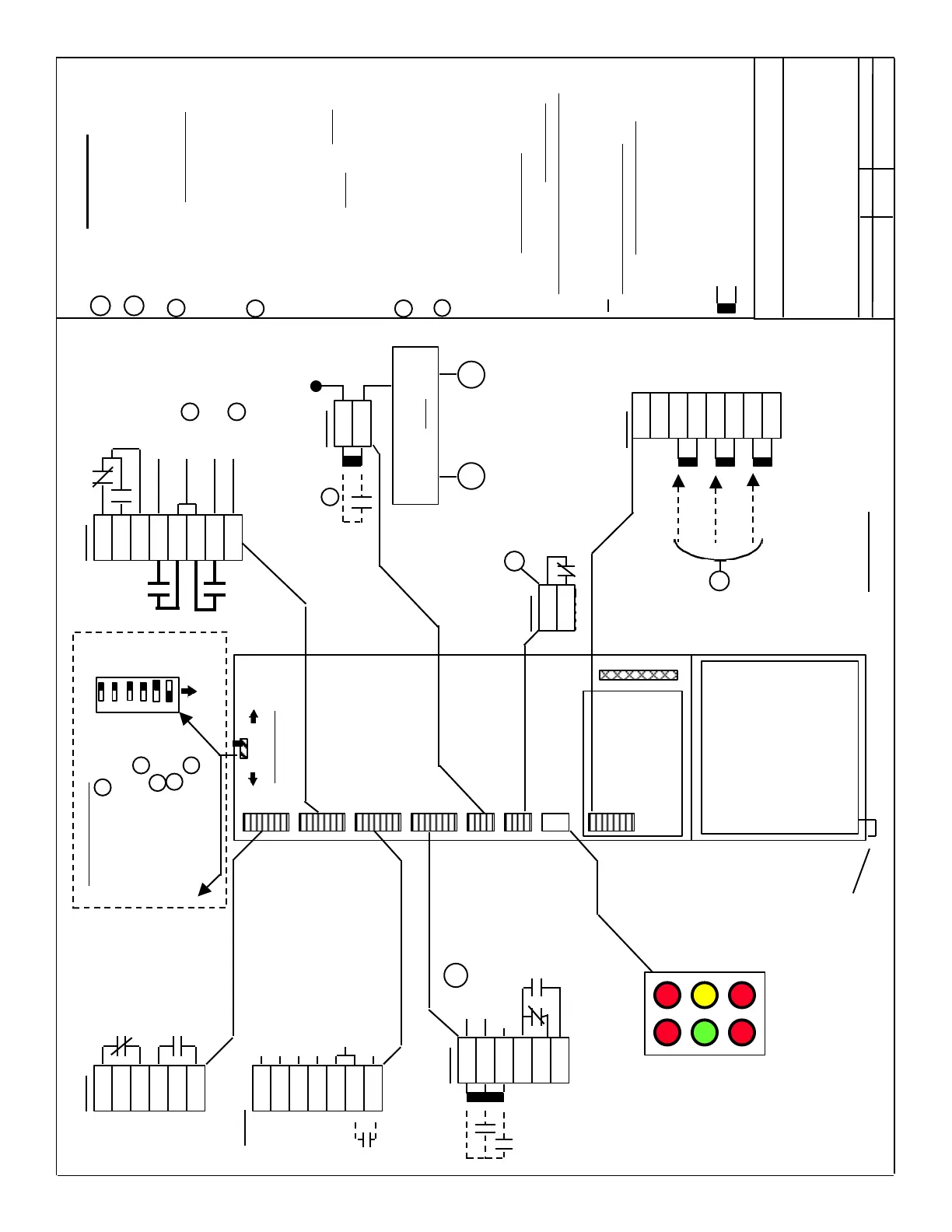
Drawing for: Interface connections
for Supply Infeed Modules
( 16, 36, & 55 KW)
Date by Revision
8 / 13 / 98 de/dk Rev. A5
74
73.2
73.1
72
X111 (6SY9896)
Ready / Fault
Status Relay
Output
(250VAC / 1 Amp.
30VDC / 1Amp.)
7
45
44
10
15
15
R
P(+)24
P(+)15
N(-) 15
N(-) 24
M (P. S. Common )
Reset
Drive’s
Internal
Power
Supplies
Set-Up / Standard Operation
Internal Line Contactor Control
LED Status
Indications
5V(Red)
Ready(Yel.)
DC Link
Over Volt.(Red)
15V(Red)
63,64 or 48(Grn)
(not enabled)
Line(Red)
X161
9
112
48
111
113
Status of the Internal
Line Contactor
FR+
X121 (6SY9897)
5.3
5.2
5.1
63
9
9
64
19
FR-
I
2
T & Motor
Over Temp.
Monitoring
(30 V / 1 Amp. )
Pulse Enable
Drive Enable
FR+
6SN1145-1B...
Supply Infeed
Module
D C Link
Cover
NOTES:
1
These functions are not included on the
10,28 KW Unregulated Modules.
2
X172
AS1
AS2
Set-up mode. Closed with power
off, or terminal 112 open.
( 250 VAC / 50 VDC / 2A Max.
5 VDC / 10ma Min.)
X172
1
This Optional Input is used only when
line voltage is supplied separately to the
the L. V. Power Supply. (1 place)
For additional information on terminal
definition, use and operation see the
“Planning Guide” (Sect. 3.7...).
Indicates Factory supplied
“Jumper”
Items shown on the left side of the
connectors are external connections
to be supplied by the installer.
# Connections shown with a “ # “ and
not connected are Optional - the one’s
shown connected are Required for
drive operation.
3
3
FR+ & FR- are internal supplies to be
used as a power source for the drive’s en-
ables(3 Places). If using an external +24V
source for controlling enables, connect the
external source’s P. S. common to Term.-19
Internal Power Source for
the Drive’s Internal Contactors
4
NS1 & NS2 are provided for non-
electronic control of the drive’s internal
power relays. They can be used in the
E-Stop circuit or in a lock-out circuit to
provide a direct interruption of the power
supplied to the internal relays. NOTE:
Terminal X161- 48 MUST be opened prior
to or at the same time as NS1 & NS2, to
provide internal shut down of the drive
circuits. ( 1 Place )
General Notes
#
#
M500
P500
2U1
1U1
2V1
1V1
2W1
1W1
X181
2
#
On - Off
Switch “S1” located
on TOP of Module
Page 2 / 4
Front & top
of Module
S1
625 V 1 600 V
Fault 2 Ready
No 3 Yes
480V 4 400V
No 5 Yes
Sine 6 Trap
3
Internal Electronic Relay
Control (via X161- 48 )
Internal
Drive
Contactors
(Precharge) ( Line)
X171
NS1
NS2
4
#
Section C
1
2
3 Regenerate to Lines 1
4 480 V operation 5
5 Controlled Infeed 1
6 Current control mode 6
Ready / Fault Relay
DC Link Voltage 1
S1 Bit Definitions
5
Adapt to line voltage. Standard setting
is for 400 V operation.
Sets type of current control mode.
Standard setting is Sinusoidal.
213
X141 (6SY9898)
(6SY9896)
(6SY9433)
(6SY9433)
(6SY9900)
6
Overvoltage
Module
See Page 3/4
DC Link Cover Shield wire
connected to bottom of module
 Loading...


