3
02.98
1-30
Siemens AG 1998 All Rights reserved 6SN1197–0AA00 02.98 Edition
SIMODRIVE 611 (PJ)
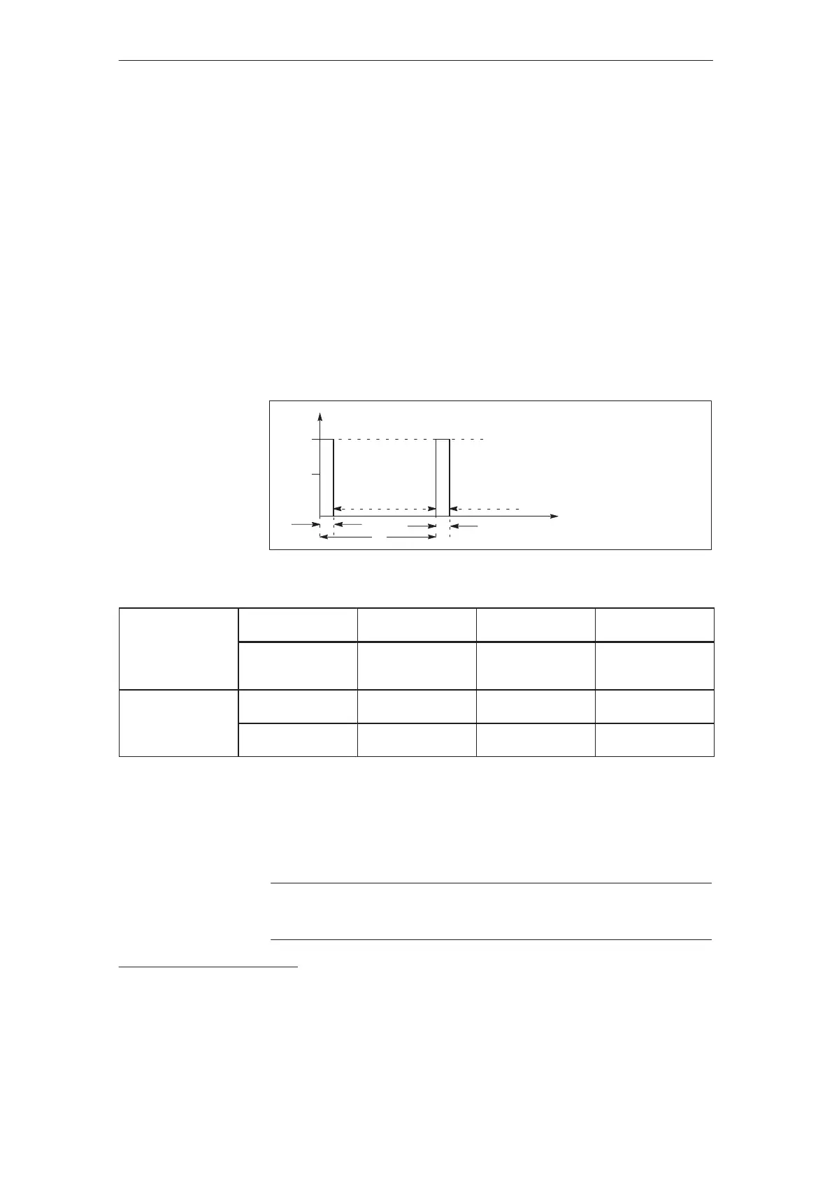
Dimensioning the load duty cycles with pulsed resistors
Des.Units Explanation
E Ws Regenerative feedback energy when braking a motor from n
2
to n
1
T s Period of the braking load duty cycle
A s Load duration
J kgm
2
Total moment of inertia (including J motor)
M Nm Braking torque
n RPM Speed
Pn W Continuous rating of the pulsed resistor
P
max
W Peak rating of the pulsed resistor
E
max
Ws Energy of the pulsed resistor for a single braking operation
t (s)
P (kW)
P
max
P
n
0 kW 0 kW
A
A
T
Figure 3-4Load duty cycle for internal and external pulsed resistors
Table 3-6 Examples
Pulsed resistor
0.2/10 kW
Pulsed resistor
0.3/25 kW
Pulsed resistor
1.5/25 kW
E
max
Pn
P
max
13500 Ws
1)
200 W
10000 W
7500 Ws
300 W
25000W
180000Ws
1500 W
25000W
Example A=
T=
0.2 s
10 s
0.12 s
10 s
0.6 s
10 s
A=
T=
1.35 s
67.5 s
0.3 s
25 s
7.2 s
120 s
All of the following conditions must be fulfilled:
1.P
max
M2πn/60
2.Emax E; E=J[(2πn
2
/60)
2
–(2πn
1
/60)
2
]/2
3.P
n
E/T
Note
For UE 5 kW and UE 10 kW, it is not possible to connect an external resistor.
1)
As a result of the mechanical dimensions, the resistor can accept a relatively high level of energy.
Engineering infor-
mation is valid for
UE 5 kW, 10 kW,
28 kW and pulsed
resistor module
Load duty cycles
for braking opera-
tions
3.2.1 Technical data, supply infeed modules