VS
07.94
1-89
Siemens AG 1997 All Rights reserved
SIMODRIVE 611A Installation and Start–Up Guide/IAA/–04.97 Edition
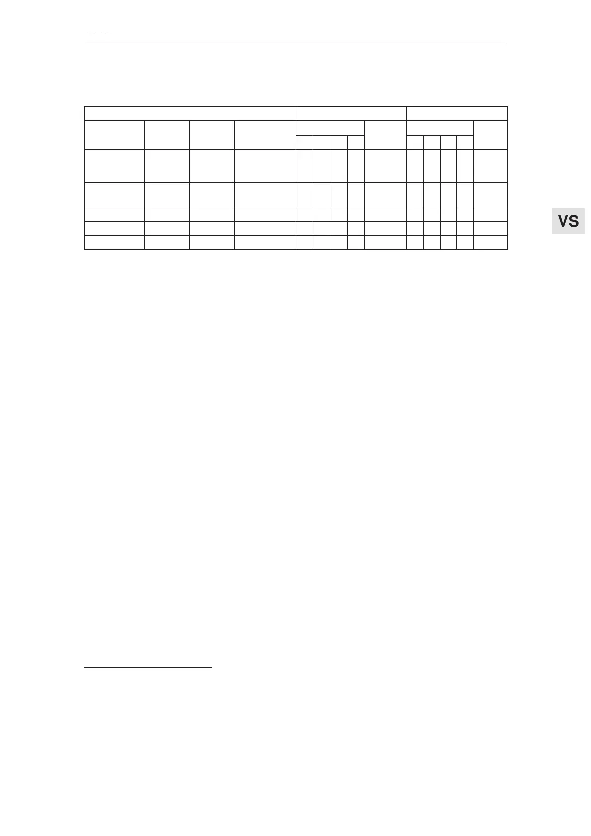
Table 1-6 adaptation table for feed module 25/50 A
Servomotor
Current limit
1)
Current controller gain
1FT M[Nm] I[A] n
td
[RPM]
Contacts
I [A]
Contacts
Kp(I)1FT... M
o
[Nm] I
o
[A] n
rated
[RPM]
2 3 4 5
I
max
[A]
6 7 8 9
K(I)
5103–VAC71
5103–VAF71
5103–VAG71
19.0
19.0
19.0
12.0
17.5
23.0
2000
3000
4000
o
o
o
o
o
o
o
o
o
o
o
o
50.0
50.0
50.0
x
x
o
x
x
x
o
o
o
o
o
x
8.0
2.5
2.0
5104–VAA71
5104–VAC71
37.0
37.0
14.0
22.5
1200
2000
o
o
o
o
o
o
o
o
50.0
50.0
x
o
x
o
x
x
x
o
11.5
4.0
5106–VAA71 45.0 17.0 1200 o o o o 50.0 x x o x 8.0
5108–VAA71 55.0 20.5 1200 o o o o 50.0 x o o x 6.5
5132–VAA71 60.0 22.5 1200 o o o o 50.0 o x o x 7.5
1)The specified value is the maximum permissible current of the particular power module – motor combination. It may be
necessary to reduce the specified value depending on the driven mechanical system.
Feed modules (VS)
04.97 1.2 Current controller settings
03.96



 To Next Page