This document provides comprehensive mounting and operating instructions for SIMOGEAR geared motors, specifically focusing on motors designed for mounting onto SIMOGEAR gearboxes. It covers various aspects from initial delivery to final disposal, ensuring safe and professional handling.
Function Description
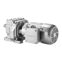
SIMOGEAR geared motors are partly completed machines intended for stationary use in general mechanical engineering applications. They comply with harmonized standards such as EN 60034 (VDE 0530) and are not approved for operation in hazardous zones. The motors are designed for surface cooling with cooling ribs, where an external fan draws air over the stator housing. IC411 forced ventilation is standard, with IC416 forced ventilation available as an option. A non-ventilated variant, IC410, is also available for special cases. Condensation drain holes are provided to prevent corrosion and maintain clearances, located at the drive end (DE) and/or non-drive end (NDE) depending on the mounting position.
Motors can be optionally equipped with mechanical backstops, which permit only one direction of rotation during operation. These backstops are fitted with centrifugally operated sprags that become wear-free when the drive speed exceeds a certain threshold. Spring-operated disk brakes are also optional, electrically released to reduce motor run-on times or hold loads. These brakes are designed for DC operation and can be controlled directly by DC voltage or via a rectifier for AC voltage. L/LS brakes can be encapsulated for dust and moisture protection, and some versions offer low-wear friction linings or microswitches for brake status monitoring.
Various rotary encoders are available to sense speed and position, including DRIVE-CLiQ, incremental, and absolute encoders. Functionally safe rotary encoders are marked with a signal yellow on the fan cover and "SI04" on the rating plate. Motors can also be prepared for customer-supplied encoders, with a shaft end designed for a maximum total weight of 500g. For 4-pole motors, a free second shaft end can be supplied at the NDE, capable of transmitting full rated power. Handwheels are available for motor frame sizes 71 to 160.
The motors are designed for operation with converters, with the converter world motor or synchronous-reluctance motor being recommended. These motors typically feature an improved ("Advanced") insulating system and are controlled by the converter.
Important Technical Specifications
General Motor Data:
- Stator Winding: Designed for temperature class 155 (F), optionally 180 (H).
- Rotor Vibration: Standard grade A, finely balanced for converter world motors.
- Housing Materials: Stator housing and bearing shields made of die-cast aluminum or cast iron.
- Cooling: IC411 (standard), IC416 (optional forced ventilation), IC410 (non-ventilated).
- Ambient Temperature: Standard -20 °C to +40 °C for air-cooled versions (up to 1000m altitude).
- Degree of Protection: IP54 or higher, not suitable for outdoor use below IP54.
Backstop (FXM series):
- Minimum Drive Speed for Wear-free Operation: Ranges from >890 r/min for frame size 71/80 to >630 r/min for frame size 225/250.
- Ambient Temperature: Not suitable for temperatures under -25 °C.
Brakes (L/LS and FDX series):
- Braking Torques: Vary by brake type and speed, measured at 100 r/min. For example, L4 at 1500 r/min has 87% of rated braking torque.
- Permissible No-load Speed with Emergency Stop: Ranges from 6000 r/min for L4/LS4 to 1800 r/min for L150/LS150.
- Release Times (t2): Range from 20 ms (L4/1.4) to 585 ms (L400/600).
- Application Times (t1): Range from 22 ms (L4/2) to 275 ms (L400/265).
- Weight (JB): Ranges from 0.15 kg (L4/1.4) to 200 kg (L400/600).
- Working Capacity (W1max): Ranges from 156 kJ (L4/1.4) to 6480 kJ (L400/145).
- Friction Energy (Wtot): Ranges from 22 MJ (L4/2) to 1440 MJ (L400/145).
- Air Gap (sLN): Nominal values from 0.2 mm (L4/1.4) to 0.6 mm (FDX40). Maximum values for standard excitation (sLmax) and overexcitation.
- Temperature Range: Standard L brakes -20 °C to +45 °C, with C10 option down to -40 °C.
Encoders:
- DRIVE-CLiQ (AS22DQC, AM22DQC):
- Supply Voltage: 20.4 ... 28.8 VDC.
- Resolution: 22 bits (absolute), 12 bits (absolute).
- Max Mechanical Speed: 4500 r/min.
- Degree of Protection: IP66.
- Weight: 0.4 kg.
- Incremental (HTL, TTL):
- Pulses per Revolution: 1024 or 2048.
- Supply Voltage: 5 VDC ±10% or 10 ... 30 VDC.
- Max Mechanical Speed: 5000 r/min.
- Degree of Protection: IP66/IP67.
- Weight: 0.22 kg to 0.34 kg.
- Absolute (1XP8014, 1XP8024):
- Supply Voltage: 5 V ±5% or 10 ... 30 V.
- Positions per Revolution: 8192 (13 bits).
- Differentiable Revolutions: 4096.
- Max Mechanical Speed: 6000 r/min.
- Degree of Protection: IP66.
- Weight: 0.3 kg.
- Rugged Encoders (Leine und Linde, Hübner): Designed for harsh conditions, shock and vibration proof, with insulated bearings.
External Fan:
- Volume Flow: Ranges from 78 m³/h (size 71, 50 Hz) to 1860 m³/h (size 250, 60 Hz).
- Rated Voltage Range: Varies by size and phase (1AC or 3AC).
Usage Features
- Installation Flexibility: Motors can be mounted in various positions, with specific considerations for condensation drainage.
- Connection Options: Terminal boxes allow for star or delta connections, with clear diagrams provided. Shielded cables are recommended for converter operation.
- Converter Operation: Optimized for vector control mode, with improved insulation for AC voltages up to 500 V.
- Safety Functions: Optional functionally safe encoders and holding brakes for safety-relevant applications.
- Direction of Rotation: Motors are suitable for both clockwise and counter-clockwise rotation, with clear marking for single-direction applications (e.g., with backstop).
- Documentation: Comprehensive documentation is available online, including technical data, circuit diagrams, and spare parts lists.
Maintenance Features
- Regular Inspections: Brakes require regular inspection, adjustment, or replacement due to wear.
- Air Gap Check: Procedures for checking and adjusting the brake air gap are detailed, with specific values for standard and overexcitation.
- Friction Lining Replacement: Instructions for replacing the friction lining of the brake are provided, including steps for disassembling and reassembling components.
- Lubrication: Bearings are permanently lubricated (2Z bearings). For open bearings (1Z bearings), special greases are used, and grease replacement is recommended every 3-4 years.
- Cleaning: Regular removal of dust from the motor is crucial to prevent overheating and potential explosion hazards. High-pressure cleaning is explicitly prohibited.
- Fastening Bolt Tightness: All fastening bolts should be checked for tightness using a torque wrench at regular intervals.
- Insulation Resistance Test: Recommended before commissioning and after long storage periods to ensure winding integrity.
- Spare Parts Availability: Siemens offers original spare parts and accessories, with detailed lists and an online service ("Spares on Web") for easy ordering.