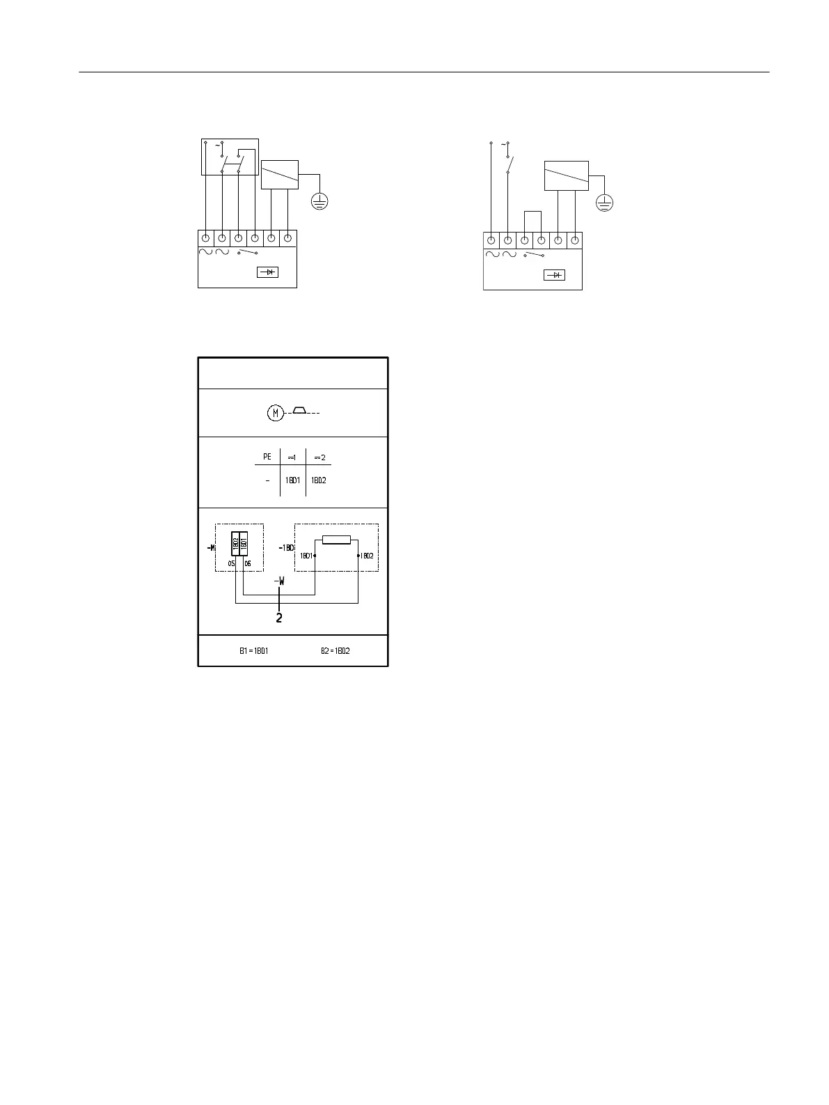
+ -
U
Brake
Rectifier
G_D087_DE_00046
Function circuit diagram of a brake switched on the
DC and AC sides
+ -
U
Brake
Rectifier
G_D087_DE_00048
Function circuit diagram of a brake switched on the
AC side
Figure6-4 Circuit diagram A01BD000 (326592)
6.6.9 External fan (optional)
Please note the direction of rotation. The direction of rotation is indicated by an arrow on the
external fan.
Connect up the external fan according to the applicable circuit diagram.
Before commissioning the motor, check that the external fan is working properly.
The external fan must be switched on during motor operation.
After the motor has been switched o, the external fan must continue to run, depending on
the temperature.
Mounting
6.6Connecting the motor in the terminal box
Motors for mounting onto SIMOGEAR gearboxes
Operating Instructions, 01/2024, A5E53220841A/RS-AA 77



 To Next Page