In the case of the converter world motor, do not change the star or delta connection. The
MLFB and the motor data contain information about the connection method.
Select the connection cables according to DINVDE0100. Take into account the rated current
and the plant-specic conditions. Shielded cables are used for motors that are operated with
a converter.
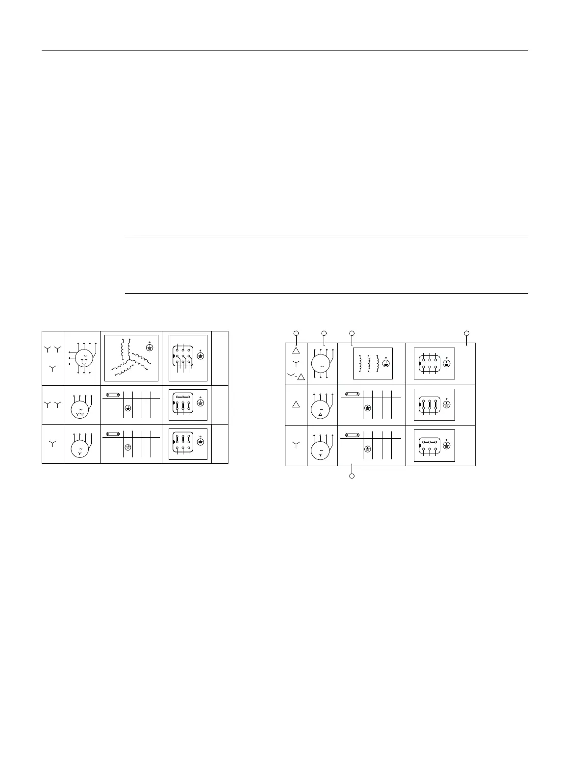
The following required information for connection is specied in the technical data:
• Direction of rotation
• Number and arrangement of the connections
• Circuit/connection of the motor winding.
Note
High starting currents occur when starting three-phase motors connected directly to the line
supply Use the star-delta starting connection to reduce these. Comply with local regulations
when doing this. Alternatively, motors can be operated with a soft starter or a converter.
-M
U WV
-M
U1 W1V1
U2 W2V2
U3 W3V3
-M
U WV
=T1 U1
=T2 V1
=
T3
W1
=
=
T4
T7
U2
U3
=
=
T5
T8
V2
V3
=
=
T6
T9
W2
W3
=T1 U
=T2 V
=T3 W
=T1 U
=T2 V
=T3 W
U
L3L2L1PE
[U2,V2,W2];
[W1,W3]
[V1,V3];
[U1,U3];
V W
U
L3L2L1PE
[V2,V3];
[U2,U3];
[W2,W3]
V W
U1 V1 W1 PE
U2 V2 W2
U3
V3
W3
3
M
3
U V W PE
M
PE
U V W
3
M
U1
U2
U3
W3
W2
V1
V3
W1
V2
Circuit diagram_YY-Y
G_D087_DE _00 045
T1 = U1
T2 = V2
T3 = W1
T4 = U2
T5 = V2
T6 = W2
T1 = U
T2 = V
T3 = W
T1 = U
T2 = V
T3 = W
U V W PE
3
M
U V W PE
3
M
U2 V2 W2 PE
U1 V1 W1
3
M
U
L3L2L1PE
[U2,V2,W2] V W
U
L3L2L1PE
[U2,V1];
[V2,W1]
[U1,W2];
V W
-M
U1 W1V1
W2 U2 V2
-M
U WV
-M
U WV
U2 W2V2
U1 W1V1
1 2 3
5
4
Motor connection Δ/Y
Mounting
6.6Connecting the motor in the terminal box
Motors for mounting onto SIMOGEAR gearboxes
70 Operating Instructions, 01/2024, A5E53220841A/RS-AA