Electrical connection
8.3 System integration
1FK2 synchronous motors for SINAMICS S120
Configuration Manual, 06/2019, A5E46927724B AB
107
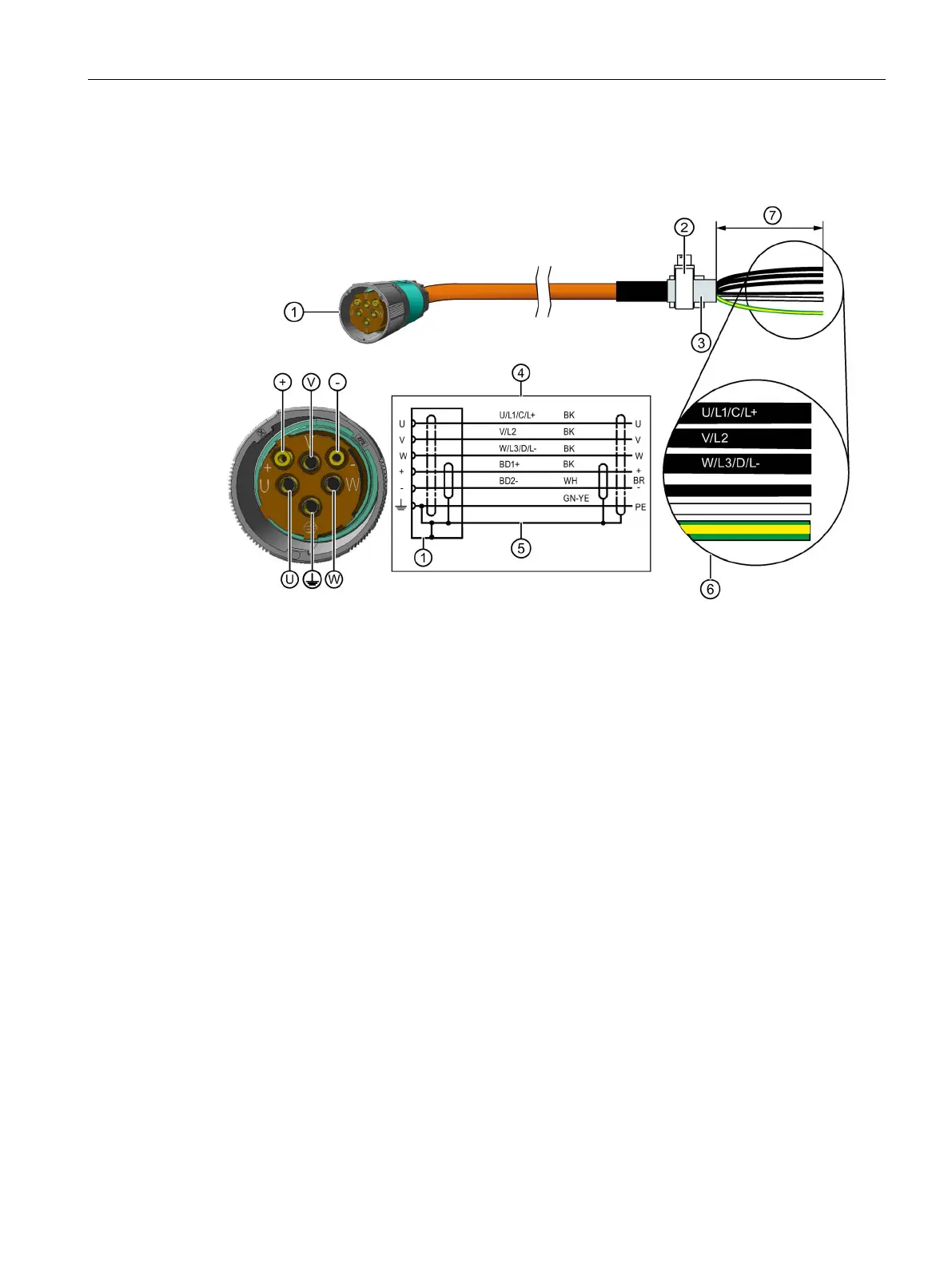
For connector size M40
SPEED-CONNECT connector, size M40
Terminal for the cable shield
Connection diagram
U; V; W = power cables, 1.5 mm
2
, each cable with separate shielding
BD1+ and BD2- = brake cable without lettering, 1.5 mm
2
, shielded together
PE = protective conductor
Recommended length of the cable ends: 105 mm
Lock the round connector properly on the motor
Information on locking is provided in Chapter "Handling the quick-action locking (Page 108)".

 Loading...


