Connecting
5.4 System integration
1FK7 G2 synchronous motors
70 Operating Instructions, 05/2021, A5E50907562B AA
Rotatability of the connectors for motors without DRIVE-CLiQ interface and for motors with
DRIVE-CLiQ interface via Sensor Modules
1FK7□□□-□□□□□-□X□□; X = A, D, E, F, K, L, N
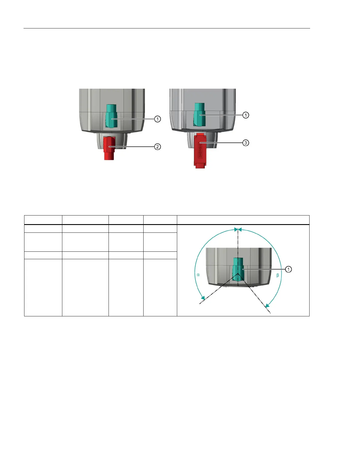
M23 or M40 power connector
Signal connector without DRIVE-CLiQ
Signal connector with DRIVE-CLiQ and Sensor Module (SMI)
Rotation range of the power connector ①
1FK706
1FK710
Rotation range of the power connector ①