Addresses of digital modules
The address of an input or output of a digital module is made up of the byte address and the
bit address.
HJ
,QSXW%\WHDGGUHVV%LWDGGUHVV
,
Figure 7-2 Address of an input of a digital module - example
The byte address is governed by the module start address.
You can note the bit address on the module.
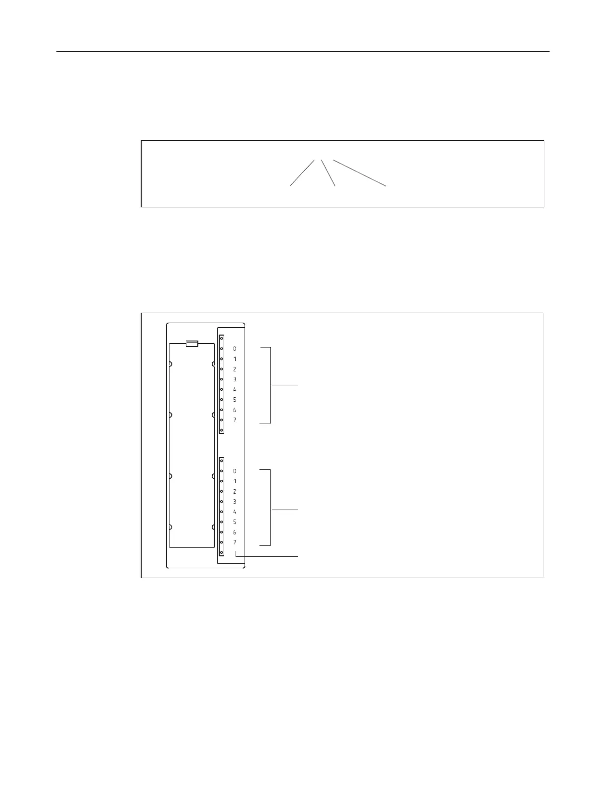
The figure below shows you the scheme by which the addresses of the individual channels of
the digital module are obtained.
%\WHDGGUHVV
0RGXOHVWDUWDGGUHVV
%\WHDGGUHVV
0RGXOHVWDUWDGGUHVV
%LWDGGUHVV
Figure 7-3 Addresses for the inputs and outputs of digital modules
Example of digital modules
The example in the figure below shows which default addresses are derived when a digital
module is located in slot 4 (that is, when the module start address is 0).
Slot number 3 is reserved as no interconnection module is present in the example.
Addressing
7.3 Addressing signal modules
SIMOTION C
Operating Instructions, 11/2016, A5E33441428B 131