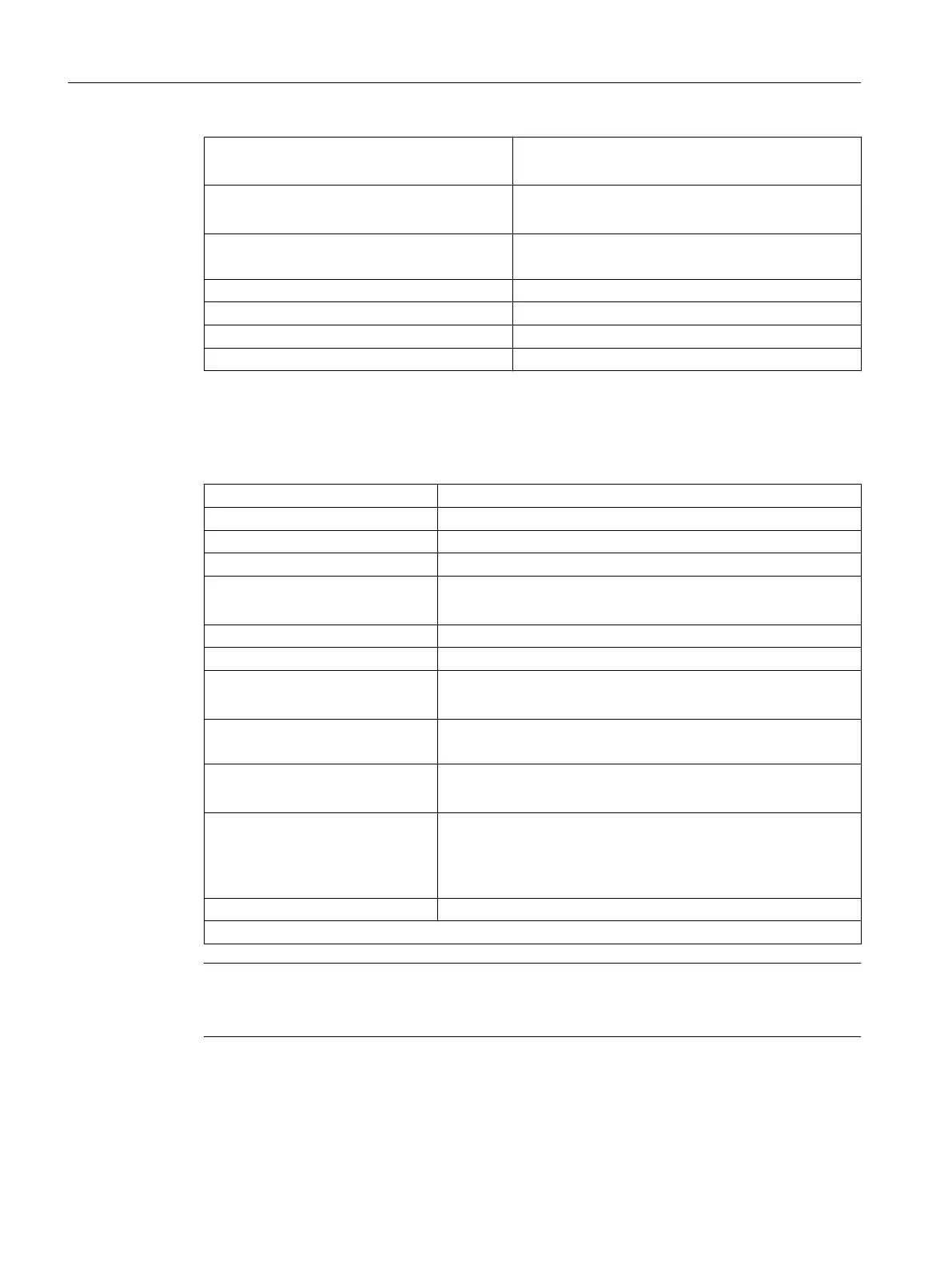
Input current
● 0 signal: 15 mA
● 1 signal: 6 to 30 mA (typically 8 mA)
Input delay (I0 to I11, B1 to B4, M1 to M2)
● 0 → 1 signal: 15 μs (typically 6 μs)
● 1 → 0 signal: 150 μs (typically 40 μs)
Connection of a 2-wire encoder
Permissible quiescent current
Supported
2 mA
Electrical isolation between inputs No
Electrical isolation between inputs and logic Yes
Insulation 500 V DC
Length of cable Max. 30 m
Digital outputs
Table 11-14 Digital outputs
Number of outputs 8
Supply voltage 24 V DC (permissible range: V
L
= 20.4 to 28.8 V)
Output voltage 1 signal: From V
L
1)
- 0.8 V to V
L
1)
V
Max. output current 1 signal: 5 mA. to 0.6 A (via supply voltage)
Total current of the outputs
● max. 4 A (at 0 to 40° C)
● max. 2 A (at 40 to 55° C)
Extinguishing energy per output 400 mJ (not simultaneous)
Lamp load 5 W
Switching rate
● 100 Hz (with resistive load)
● 2 Hz (with inductive load)
Short-circuit protection
Max. leakage current
Yes
0 signal: 2 mA
Output delay (Q0...Q7)
● 0 → 1 signal: 500 μs (typically 150 μs) with RL = 60 Ohm
● 1 → 0 signal: 500 μs (typically 150 μs) with RL = 60 Ohm
Electrical isolation between outputs
Electrical isolation between out‐
puts and logic
Insulation
No
Yes
500 V DC
Length of cable Max. 30 m
1) V
L
- Supply voltage of outputs
Note
The connecting cable between the voltage source and the load current supply connector L+
and the associated reference potential M should not exceed a maximum length of 10 m.
Technical data
11.1 Technical data
SIMOTION C
168 Operating Instructions, 11/2016, A5E33441428B