● Teleservice adapter
● Gateways
Note
All released modules and devices are listed in the PM 21 Catalog and in chapter I/O
modules approved for SIMOTION (Page 21). This documentation is supplied in electronic
format with SIMOTION SCOUT. Take note of the documentation on the individual modules
or devices!
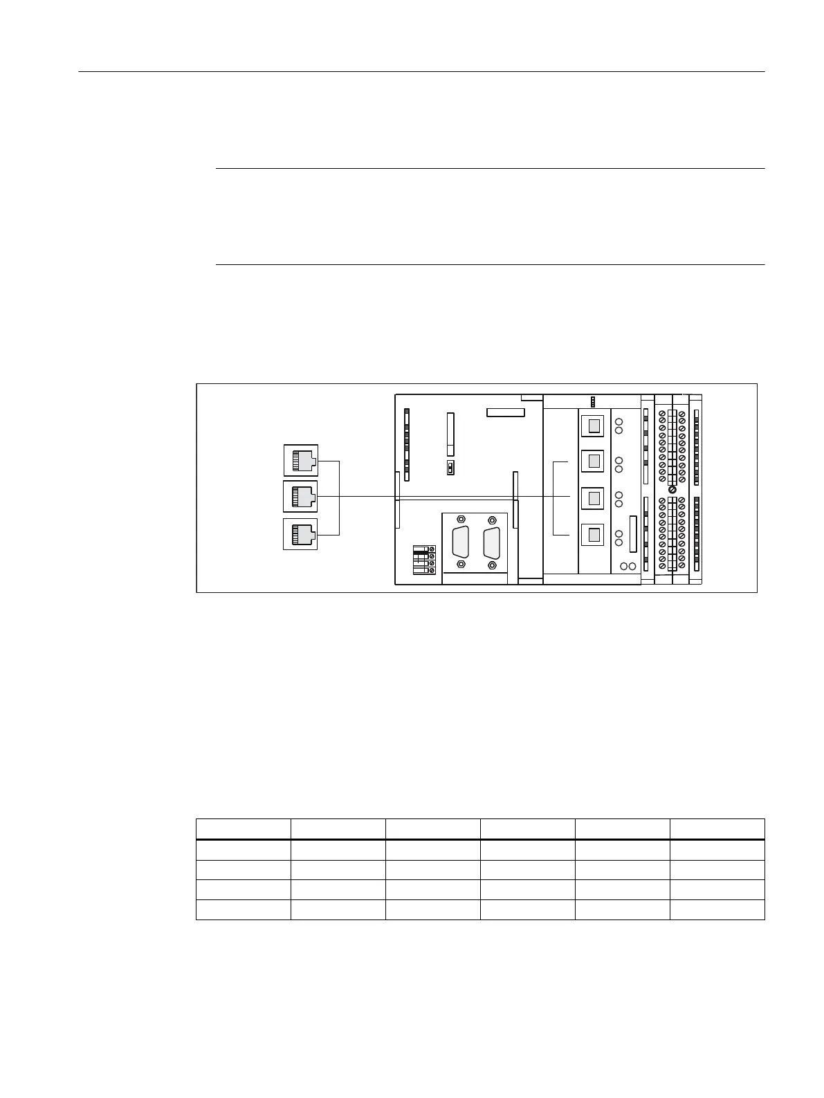
Interface position
The following figure shows the mounting position and the designation of the PROFINET IO
interface on the module.
;
;'303,
;'3
&31
6,(0(16
581
6723
05(6
;3
;3
;3
6<1&)$8/7
;
,(
;
31
,(
3
3
3
$8$%$$
Figure 4-3 X11 interface position (C240 PN), three ports P1, P2, P3
The following LED displays are arranged behind the front cover of the SIMOTION C240 PN.
For a description of the LED displays, see section Display elements (Page 39).
Interface assignment
Designation: X11 (PROFINET), three ports P1, P2, P3
Type: 8-pin RJ45 socket
Table 4-3 X11 interface assignment (ports P1, P2, P3)
Pin Name Type Pin Name Type
1 TDP O 5 Not assigned
2 TDM O 6 RDM I
3 RDP I 7 Not assigned
4 Not assigned 8 Not assigned
Signal names
RDP, RDM - Receive Data +/-
Interfaces
4.3 PROFINET interface (C240 PN)
SIMOTION C
Operating Instructions, 11/2016, A5E33441428B 45