Wiring diagram and block diagram
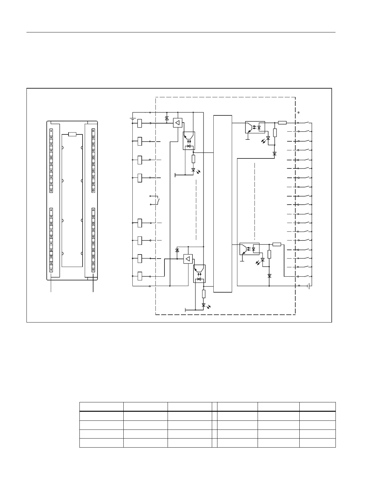
The following figure shows the terminal diagram and block diagram for digital inputs/outputs
on the SIMOTION C.
6WDWXVGLVSOD\V
,QWHUQDOEDVLFFLUFXLW
6,027,21&
JUHHQ
9
0
%
%
%
%
0
/
9
0
LQSXW
0
RXWSXW
0
0
0
0
Figure 4-14 Terminal and block diagram of digital inputs/outputs on the SIMOTION C
Connector pin assignment
Connector designation: X1
Connector type: 40-pin S7 front connector for single-wire connection
Table 4-17 Front connector X1 pin assignment
Pin Name Type Pin Name Type
1 L+ VI 21 Unassigned
2 Q0 DO 22 B1 DI
3 Unassigned 23 B2 DI
4 Q1 DO 24 B3 DI
Interfaces
4.8 I/O interface
SIMOTION C
70 Operating Instructions, 11/2016, A5E33441428B