Options 08.96
6-10 Siemens AG 6SE7087-6BM70
SIMOVERT MASTER DRIVES Operating Instructions
6.6.1.2 Bypass contactor with I/R unit
NOTE
If individual inverters have to be isolated when the DC busbar is supplied through an input/regenerative
feedback unit, the the appropriate parameter sets of the infeed/regenerative feedback unit must be
simultaneously switched-over using the binary input. An optimization run for each required constellation must
be executed to determine the appropriate parameters. A maximum of four parameter sets can be selected.
If the DC busbar is to be fed from an infeed/regenerative feedback unit, the control parameter values must be
determined for this infeed/regenerative feedback unit.
During commissioning, the following steps are required:
♦
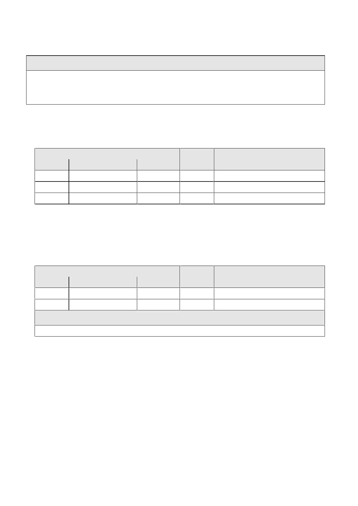
Re-parameterization for the optimization run:
Parameter- Terminal Information
No. Name Value
P629, i001
ST.BC energized 0000 X9: 4,5
P612, i001
ST.BC energized 1001 X9: 4,5
P600, i001
ST. ready to switch-on 1001 X9: 4,5 Bypass contactor closes
Table 6.12 Parameterization for the optimization run
♦
Execute the optimization run to determine the values for the closed-loop control parameters for the
infeed/regenerative feedback unit (
+
Instruction Manual, infeed/regenerative feedback unit).
♦
Re-parameterize for operation with the bypass contactor:
Parameter- Terminal Information
No. Name Value
P600, i001
ST.ready-to-switch-on 0000 X9: 4,5
P629, i001
ST.BC energiz. 1001 X9: 4,5
NOTE
In this case, the converter must be externally supplied with 24 V DC (connector -X9: 1,2)
Table 6.13 Parameterization for the bypass contactor (electrical DC link coupling)