Connecting-up 08.96
3-4 Siemens AG 6SE7087-6BM70
SIMOVERT MASTER DRIVES Operating Instructions
Type of Order No. Max. cross-section Gland
construc.
(mm
2
) acc. to VDE MCM
J 6SE70_._.-._._J20 4
×
300 4
×
800 M16
K 6SE70_._.-._._K20 4
×
300 4
×
800 M16
M 6SE70_._.-._._M20 8
×
300 8
×
800 M16
Table 3.2 Maximum cross-section and gland
3.1.1 Protective conductor connection
The protective conductor should be connected-up on both the supply- and motor sides. It should be dimensioned
according to the power connections.
3.2 Auxiliary power supply/main contactor or bypass contactor
The auxiliary power supply and the main- or bypass contactor are connected through the 5-pin connector X9.
Connector X9 is supplied together with the connectors for the control terminal strip. Cables from 0.2 mm
2
to
2.5 mm
2
(AWG: 24 to 14) can be connected to X9.
The auxiliary power supply is required if the drive converter is fed
through a main- and bypass contactor.
The main- or monitoring contactor is controlled through floating contacts
-X9.4 and -X9.5 (software pre-setting).
More detailed information is provided in the Section „options“.
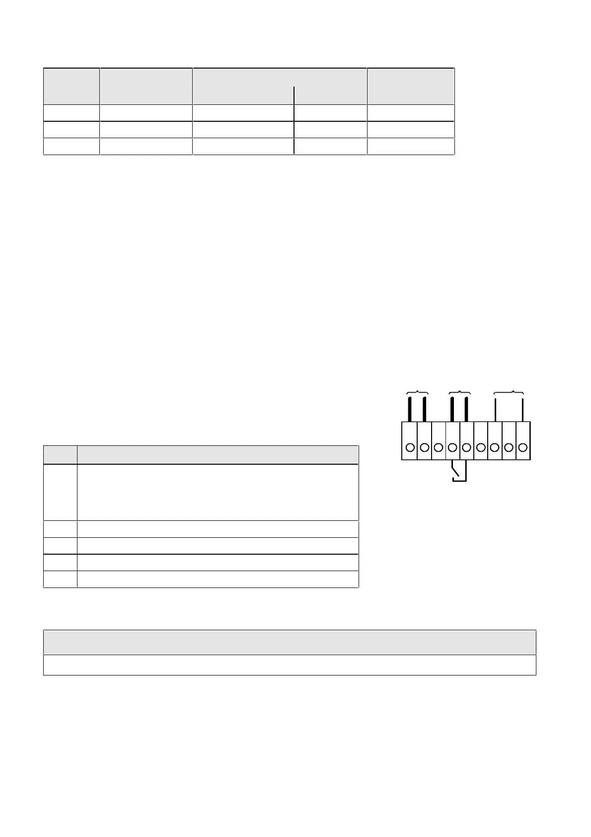
Term. Function description
1 Types of construction J and K 24 V DC external
≥
5 A (max.
8 A dependent on the options)
Type of construction M 24 V DC external
≥
10 A (max.
16 A dependent on the options)
2 Reference potential to DC
3 Unassigned
4 Main contactor control
5 Main contactor control
Table 3.3 Connector assignment for -X9
NOTES
The main contactor coil must be provided with overvoltage limiters, e.g. RC element.
12345
-X9
P
M
Ext. 24 V
DC PS
AC 230 V
1 kVA
6 789
230 V
fan
Main contactor
control
Fig. 3.1 Connecting an external 24 V
power supply and main contactor
control