Installing
3.3 Power losses and air cooling requirements
Power Module PM240-2
28 Hardware Installation Manual, 01/2020, A5E33294624B AL
3.3 Power losses and air cooling requirements
Cooling requirements
To protect the components from overheating, the control cabinet requires a cooling air flow,
which depends on the power loss of the individual components.
Formula for calculating the cooling airflow:
airflow [l/s] = power loss [W] * 0.86 / ΔT [K]
Power loss:
Total of the power losses of the individual components.
Δ T:
Permissible temperature rise i
n the control cabinet
Measures in order to ensure that the components are adequately cooled
Add the power losses of the
individual components.
– Power Module data:
"Technical data (Page 73)".
– The Control Unit power loss is
less than 0.04 kW.
– Use the manufacturers data for
components, for example
reactors or filters
Calculate the air flow required,
using the formula above.
Ensure that the control cabinet is
appropriately ventilated and
equipped with suitable air filters.
Ensure that the components
maintain the specified clearances
with respect to one another.
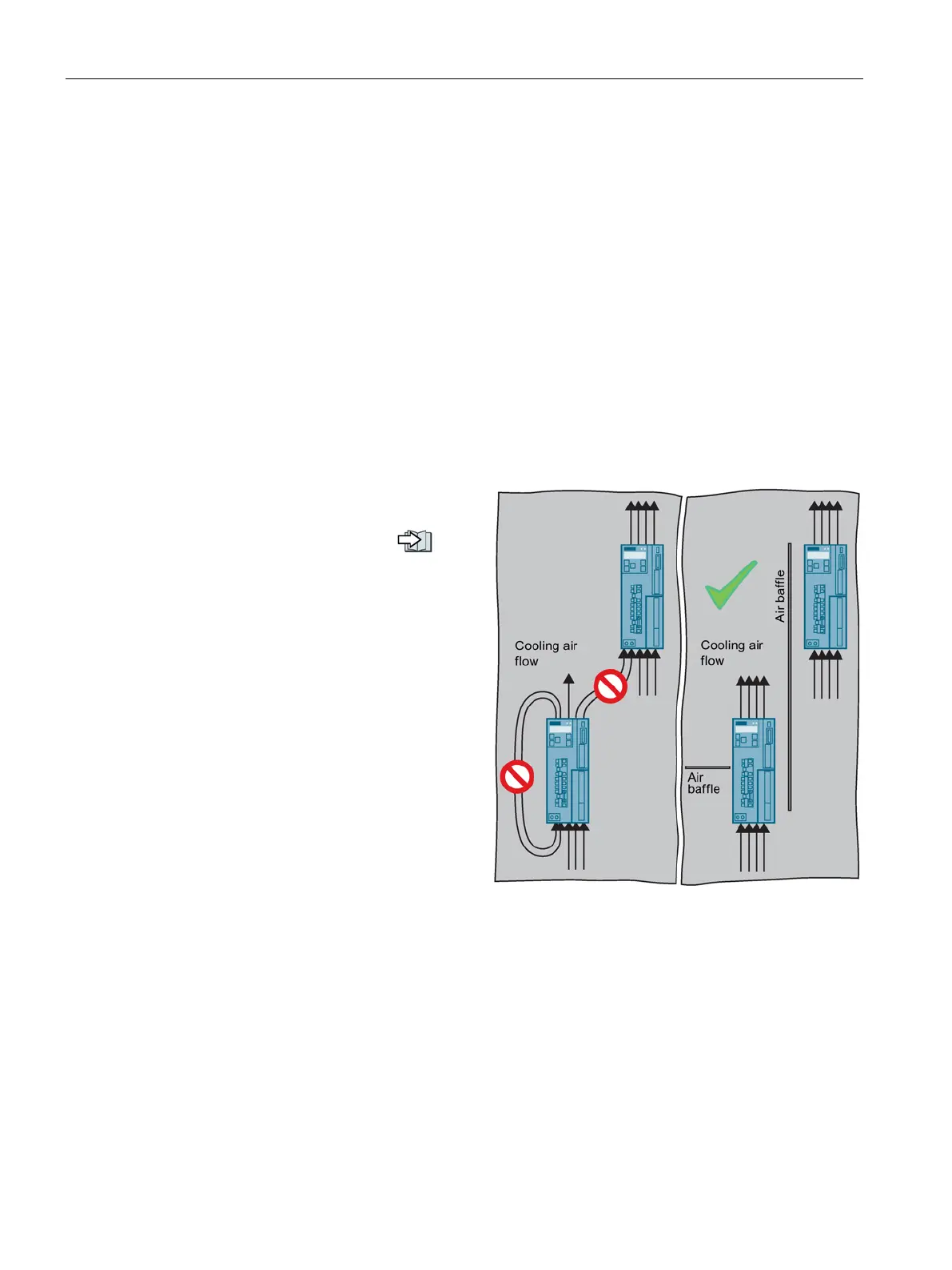
Ensure that the components are provided with adequate cooling air through the cooling
openings.
Use the appropriate air barriers to prevent cooling air short circuits
Power loss for Power Modules with push-through technology - PT devices
When you use PT Power Modules, the majority of the power loss is dissipated through the
heatsink located outside the control cabinet.

 Loading...


