Connecting
4.2 Connecting the line and motor cable at the converter
Power Module PM240-2
62 Hardware Installation Manual, 01/2020, A5E33294624B AL
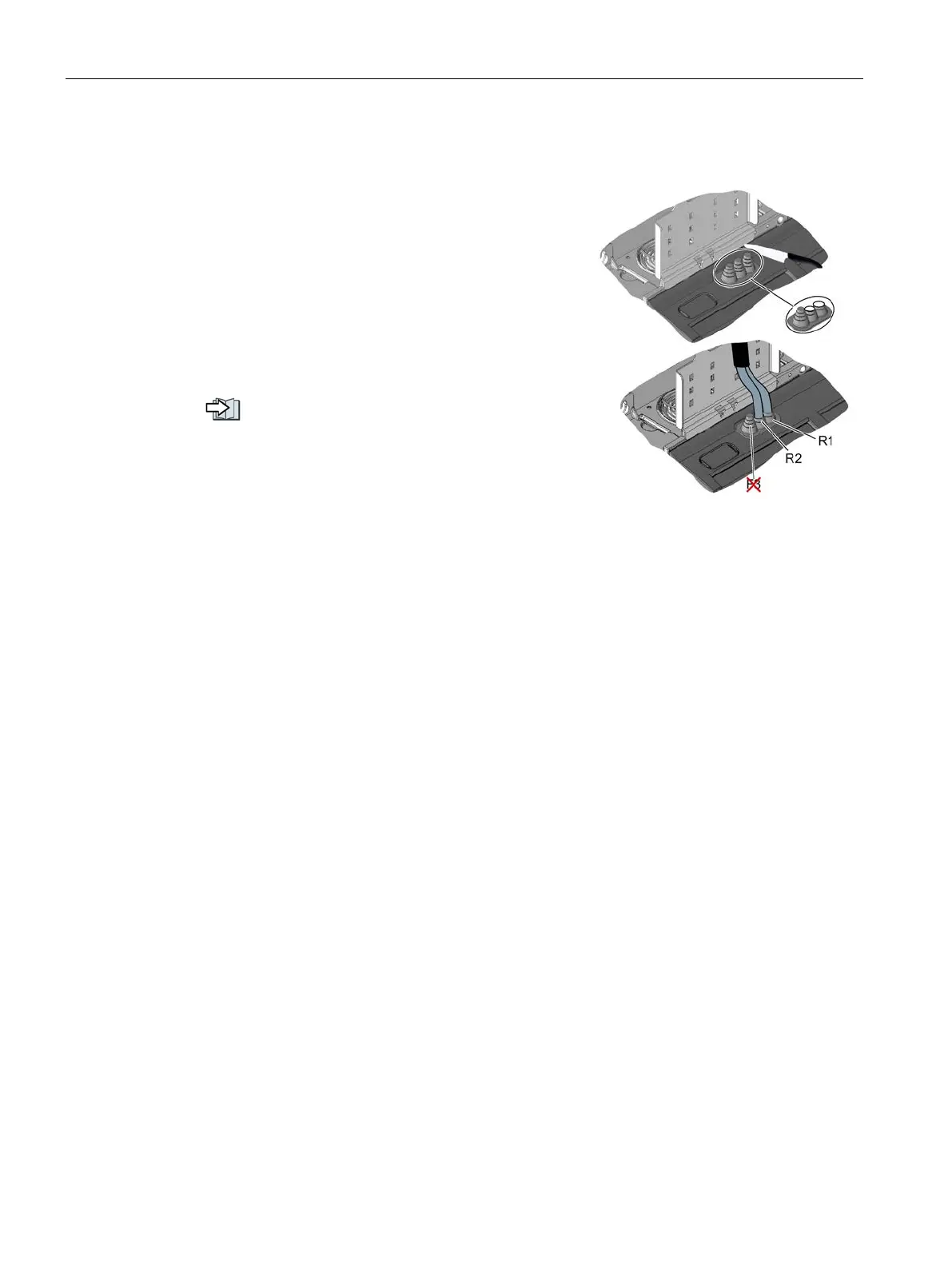
Braking resistor connection
Use the rubber cable gland as shown in the right
-
hand figure for connecting the braking re
sistor.
Using a sharp knife, cut the cap of the cable gland
corresponding
to the diameter of the connection ca-
ble of the braking resistor and establish the connec-
tions.
Connect the braking resistor at the R1 and R2 termi-
nals.
An optional shield plate is av
ailable as strain relief for
the connection cable of the braking resistor
.
Top shield plate - FSD … FSG (Page 117)

 Loading...


