Parameter list
7.2 Parameter list
SINAMICS V20 Inverter
178 Operating Instructions, 07/2012, A5E03728167
Parameter Function Range Factory
default
Can be
changed
Scaling Data
set
Data
type
Acc.
Level
P1300 = 5,6: V/f for textile applications
• Slip compensation disabled.
• Imax controller modifies the output voltage only.
• Imax controller does not influence the output frequency.
P1300 = 7: V/f with quadratic characteristic and Economy Mode
• Quadratic characteristic with Economy Mode
• Modifies the output voltage to reduce power consumption
P1300 = 19: V/f control with independent voltage setpoint
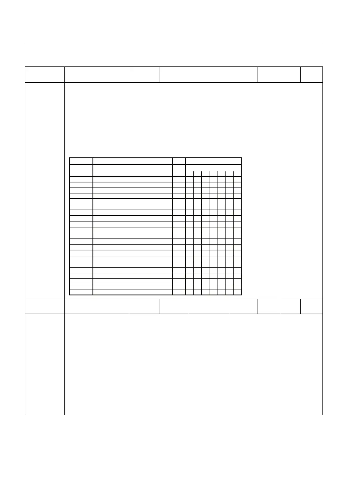
The following table presents an overview of control parameters (V/f) that can be modified in relationship to
P1300 dependencies:
01235619
2xxxxxxx
2xxxxxxx
2xxxxxxx
2xxxxxxx
3xxxxxxx
3
−−−
x
−−−
3
−−−
x
−−−
3
−−−
x
−−−
3
−−−
x
−−−
3
−−−
x
−−−
3
−−−
x
−−−
3
−−−−−−
x
3
−
x
−−−
x
−
2xxxx
−−−
2xxxx
−−−
3xxxx
−−−
3xxxxxxx
3xxxxxxx
3xxxxxxx
3xxxxxxx
3xxxxxxx
Par No. Level
V/f
Parameter name
&RQWUROPRGH
&RQWLQXRXVERRVW
$FFHOHUDWLRQERRVW
6WDUWLQJERRVW
%RRVWHQGIUHTXHQF\
3URJUDPPDEOH9IIUHTFRRUG
3URJUDPPDEOH9IYROWFRRUG
3URJUDPPDEOH9IIUHTFRRUG
3URJUDPPDEOH9IYROWFRRUG
3URJUDPPDEOH9IIUHTFRRUG
3URJUDPPDEOH9IYROWFRRUG
&,9ROWDJHVHWSRLQW
6WDUWIUHTXHQF\IRU)&&
6OLSFRPSHQVDWLRQ
&26OLSOLPLW
5HVRQDQFHGDPSLQJJDLQ9I
,PD[IUHTFRQWUROOHUSURSJDLQ
,PD[FRQWUROOHULQWHJUDOWLPH
,PD[FRQWUROOHUSURSJDLQ
,PD[YROWDJHFWUOLQWHJUDOWLPH
9ROWDJHVRIWVWDUW
3>@
P1300 =
3>@
3>@
3>@
3>@
3>@
3>@
3>@
3>@
3>@
3>@
3>@
3>@
3>@
3>@
3>@
3>@
3>@
3>@
3>@
3>@
P1310[0...2] Continuous boost [%] 0.0 - 250.0 50.0 U, T PERCEN
T
DDS Float 2
Defines boost level in [%] relative to P0305 (rated motor current) applicable to both linear and quadratic V/f
curves.
At low output frequencies the output voltage is low to keep the flux level constant. However, the output
voltage may be too low for the following:
• magnetization the asynchronous motor
• hold the load
• overcome losses in the system.
The inverter output voltage can be increased via P1310 for the compensation of losses, hold loads at 0 Hz
or maintain the magnetization.
The magnitude of the boost in Volt at a frequency of zero is defined as follows:
V_ConBoost,100 = P0305 * Rsadj * (P1310 / 100)
Note:
Rsadj = stator resistance adjusted for temperature
Rsadj = (r0395 / 100) * (P0304 / (sqrt(3) * P0305)) * P0305 * sqrt(3)

 Loading...


