Programming principles
1.6 Tool and tool offset
Turning Part 2: Programming (Siemens instructions)
74 Programming and Operating Manual, 05/2012, 6FC5398-5DP10-0BA0
The compensation is retracted with the first programmed traversing of the associated length
compensation axis.
A tool radius compensation must also be activated by G41/G42.
Programming example
Tool change:
N10 T1 ; Tool 1 is activated with the associated D1
N20 G0 X100 ; The length offset compensation is overlaid here
N30 Z100
N40 T4 D2 ; Load tool 4, D2 from T4 is active
N50 X50 Z50
N60 G0 Z62
N70 D1 ; D1 for tool 4 active, only cutting edge changed
N80 M30
Contents of a compensation memory
● Geometrical dimensions: Length, radius.
They consist of several components (geometry, wear). The control takes into account the
components to obtain a resulting dimension (e.g. overall length 1, total radius). The
respective overall dimension becomes active when the offset memory is activated.
The way in which these values are computed in the axes is determined by the tool type
and the current plane G17, G18, G19.
● Tool type
The tool type (drill or turning tool) determines which geometry data are required and how
they will be calculated.
● Cutting edge position
For the "turning tool" tool type, you must also enter the cutting edge position.
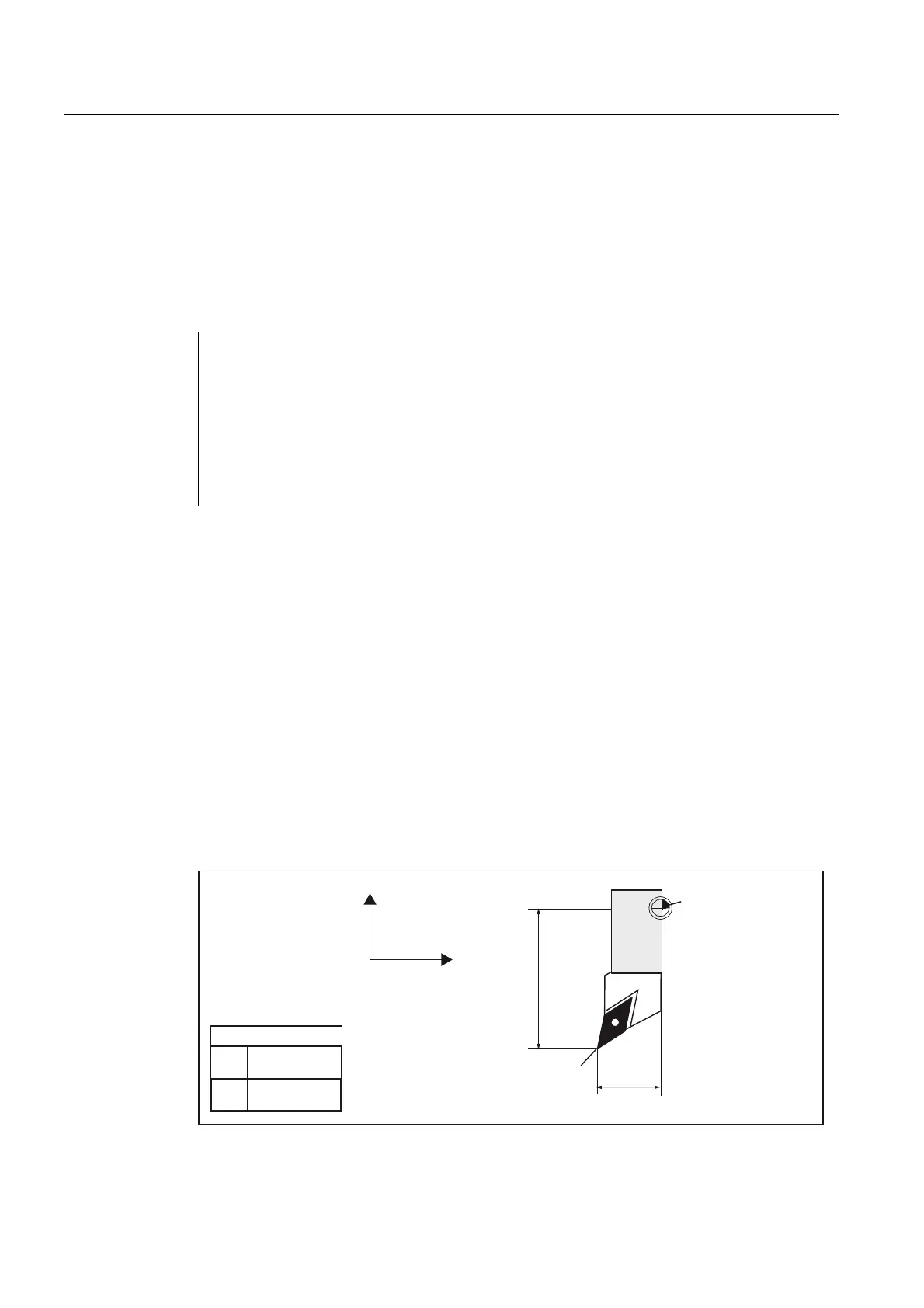
The following figures provide information on the required tool parameters for the respective
tool type.
7XUQLQJWRRO
;
=
)WRROKROGHU
UHIHUHQFHSRLQW
/HQJWK
;
/HQJWK
=
7RROWLS3
FXWWLQJHGJH
(IIHFW
*/HQJWKLQ;
/HQJWKLQ=
Figure 1-37 Tool length compensation values for turning tools