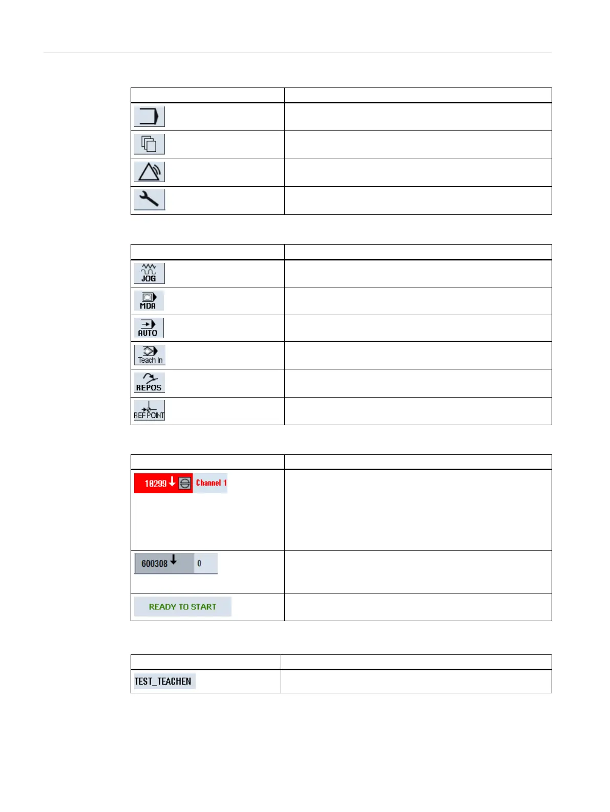
EasyManuals Logo

Siemens SINUMERIK 840D sl User Manual

Siemens SINUMERIK 840D sl
940 pages
To Next Page IconTo Next Page
To Previous Page IconTo Previous Page
Page #42 background imageLoading...
Page #42 background image
Display Description
"Program" operating area
"Program manager" operating area
"Diagnosis" operating area
"Start-up" operating area
Active mode or submode
Display Description
"Jog" mode
"MDA" mode
"Auto" mode
"Teach In" submode
"Repos" submode
"Ref Point" submode
Alarms and messages
Display Description
Alarm display
The alarm numbers are displayed in white lettering on a red
background. The associated alarm text is shown in red lettering.
An arrow indicates that several alarms are active.
An acknowledgment symbol indicates that the alarm can be ac‐
knowledged or canceled.
NC or PLC message
Message numbers and texts are shown in black lettering.
An arrow indicates that several messages are active.
Messages from NC programs do not have numbers and appear
in green lettering.
Second line
Display Description
Program path and program name
Introduction
2.4 User interface
Milling
42 Operating Manual, 08/2018, 6FC5398-7CP41-0BA0

Table of Contents

Other manuals for Siemens SINUMERIK 840D sl

Questions and Answers:

Question and Answer IconNeed help?

Do you have a question about the Siemens SINUMERIK 840D sl and is the answer not in the manual?

Siemens SINUMERIK 840D sl Specifications

General IconGeneral
Control TypeCNC
Number of AxesUp to 31
Max Number of Channels10
InterfacesEthernet, PROFIBUS, PROFINET, USB
Interpolation5-axis interpolation
Operating Temperature0°C to 45°C
Relative HumidityUp to 95% (non-condensing)
DisplayTFT color display, various sizes
Programming LanguagesDIN/ISO
Safety FeaturesSafety Integrated
PLCIntegrated PLC S7-300
Drive InterfaceSINAMICS S120
Data StorageCF card, USB
Operating SystemWindows-based

Related product manuals