03.06
2.1 Secondary electrical conditions
2-22
© Siemens AG, 2006. All rights reserved
SINUMERIK 840D Configuring Manual NCU (PHD) – 03.06 Edition
Basic insulation Safety isolation
G
3ph 400 V AC
N
Housing/shield
840D / 611 digital
1
2
3
4
10
4
4
5
6
11
S7-300 I/Os
MSTT/MCP
PCU
9
24 V
8
Person
G
7
10
11
Terminal
block
11
Motor
5
4
HHU/
HT 6
Distribution box
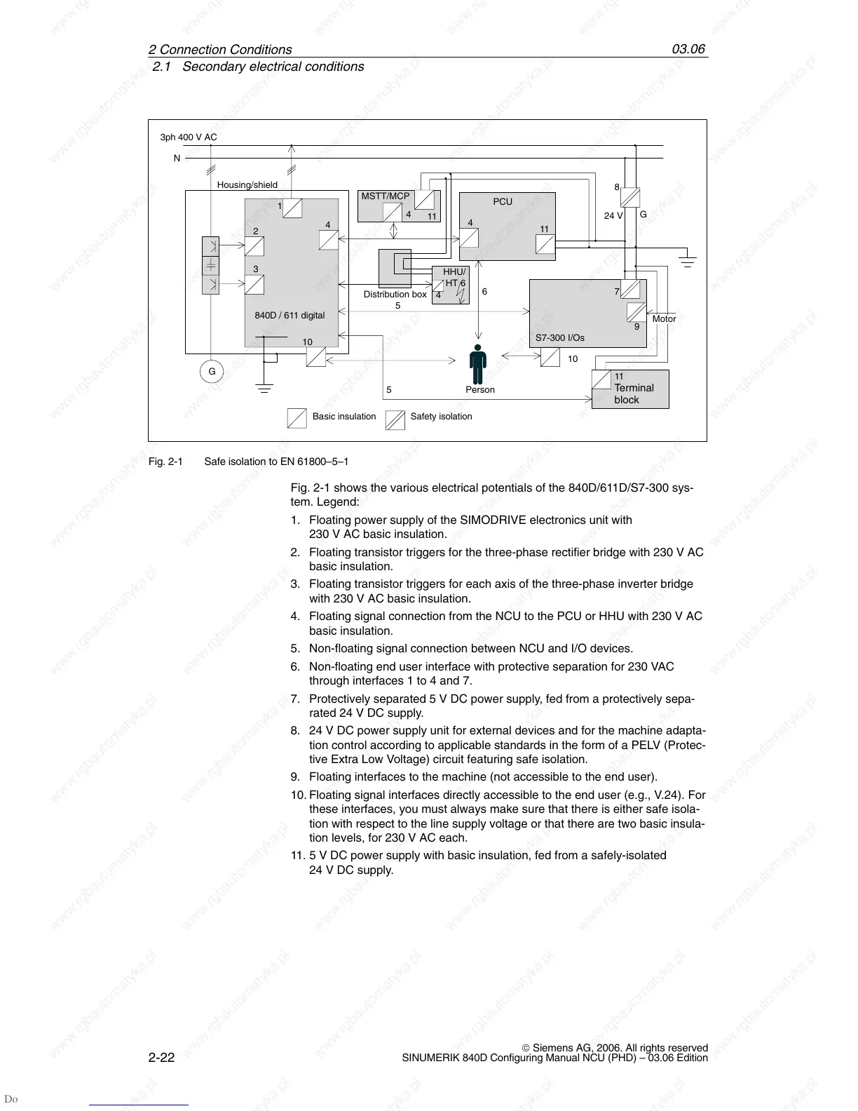
Fig. 2-1 Safe isolation to EN 61800–5–1
Fig. 2-1 shows the various electrical potentials of the 840D/611D/S7-300 sys-
tem. Legend:
1. Floating power supply of the SIMODRIVE electronics unit with
230 V AC basic insulation.
2. Floating transistor triggers for the three-phase rectifier bridge with 230 V AC
basic insulation.
3. Floating transistor triggers for each axis of the three-phase inverter bridge
with 230 V AC basic insulation.
4. Floating signal connection from the NCU to the PCU or HHU with 230 V AC
basic insulation.
5. Non-floating signal connection between NCU and I/O devices.
6. Non-floating end user interface with protective separation for 230 VAC
through interfaces 1 to 4 and 7.
7. Protectively separated 5 V DC power supply, fed from a protectively sepa-
rated 24 V DC supply.
8. 24 V DC power supply unit for external devices and for the machine adapta-
tion control according to applicable standards in the form of a PELV (Protec-
tive Extra Low Voltage) circuit featuring safe isolation.
9. Floating interfaces to the machine (not accessible to the end user).
10. Floating signal interfaces directly accessible to the end user (e.g., V.24). For
these interfaces, you must always make sure that there is either safe isola-
tion with respect to the line supply voltage or that there are two basic insula-
tion levels, for 230 V AC each.
11. 5 V DC power supply with basic insulation, fed from a safely-isolated
24 V DC supply.
2 Connection Conditions

 Loading...


