03.06
2.1 Secondary electrical conditions
2-24
© Siemens AG, 2006. All rights reserved
SINUMERIK 840D Configuring Manual NCU (PHD) – 03.06 Edition
Operator panel
front
SL
SL
Power
electronics
Machine bed
Grounding bar
Central ground connection
conductor/protective
conductor
PA
G
G
PA
Gating
electronics
NCU
SL in the motor cable
Machine
control panel
S7-300 peripherals
/single I/O module
PA
MB
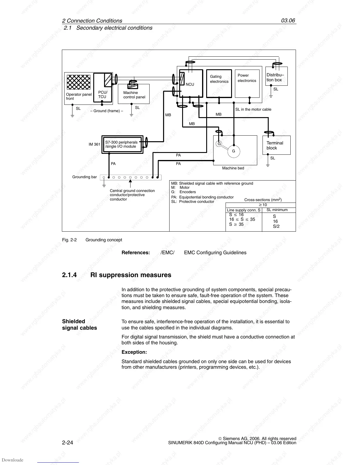
MB: Shielded signal cable with reference ground
PA: Equipotential bonding conductor
SL: Protective conductor
M: Motor
G: Encoders
– Ground (frame) –
SL
Terminal
block
SL
Distribu–
tion box
Cross-sections (mm
2
)
w10
Line supply conn. S
SL minimum
S v 16
16 v S v 35
S w 35
S
16
S/2
MB
IM 361
PCU/
TCU
MB
Fig. 2-2 Grounding concept
References: /EMC/ EMC Configuring Guidelines
2.1.4 RI suppression measures
In addition to the protective grounding of system components, special precau-
tions must be taken to ensure safe, fault-free operation of the system. These
measures include shielded signal cables, special equipotential bonding, isola-
tion, and shielding measures.
To ensure safe, interference-free operation of the installation, it is essential to
use the cables specified in the individual diagrams.
For digital signal transmission, the shield must have a conductive connection at
both sides of the housing.
Exception:
Standard shielded cables grounded on only one side can be used for devices
from other manufacturers (printers, programming devices, etc.).
Shielded
signal cables
2 Connection Conditions

 Loading...


