03.06
3.2 Installation of the SINUMERIK 840D
3-33
© Siemens AG, 2006. All rights reserved
SINUMERIK 840D Configuring Manual NCU (PHD) – 03.06 Edition
1. Remove the plastic cover over the DC link busbars by loosening it with a flat
screwdriver in the gap on the top and then folding it forward and down.
2. Remove the DC link busbars at the module to the right of the NCU box.
3. Now mount the DC link busbars from the accessory kit of the NCU box be-
tween the power module and the first drive module. Use the screws located
on the modules (observe tightening torque, M4: 1.8 Nm, M5: 3 Nm).
4. Place the cover into the matching cut-outs with the plastic lugs facing down-
ward and close the DC link by folding the cover backward until the topside
latch clicks.
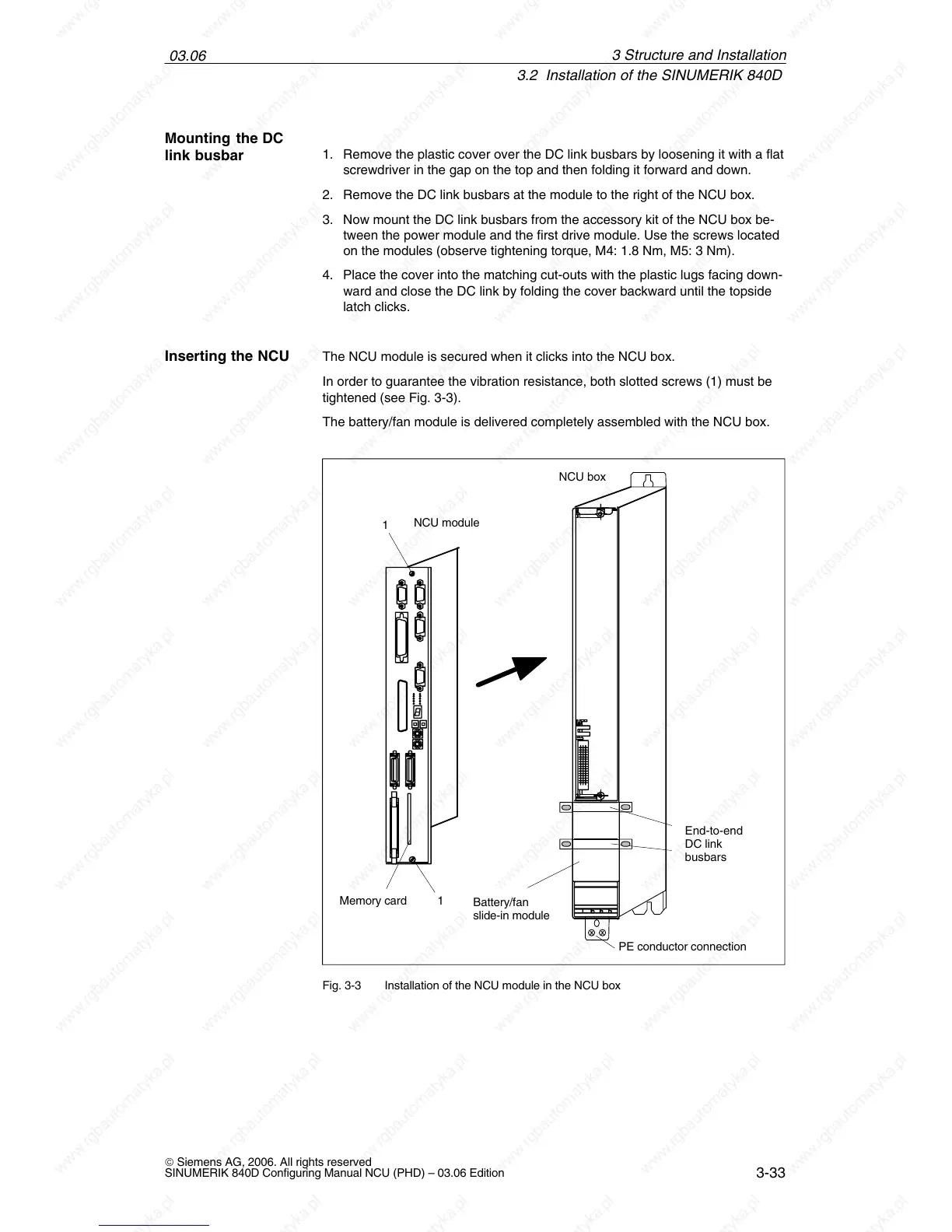
The NCU module is secured when it clicks into the NCU box.
In order to guarantee the vibration resistance, both slotted screws (1) must be
tightened (see Fig. 3-3).
The battery/fan module is delivered completely assembled with the NCU box.
Battery/fan
slide-in module
Memory card
PE conductor connection
1
1
NCU module
NCU box
End-to-end
DC link
busbars
Fig. 3-3 Installation of the NCU module in the NCU box
Mounting the DC
link busbar
Inserting the NCU
3 Structure and Installation

 Loading...


