7.2 Power supply connection
7.2.1 Requirements for the power supply
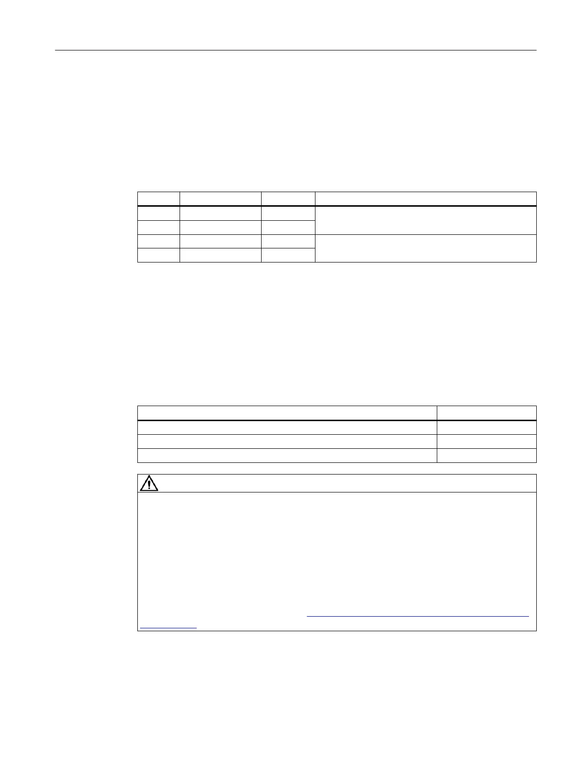
Pin assignment 4-pin screw-type connector
Pin Signal name Signal type Meaning
+/- P24 VI 24 VDC power supply (bridged)
+/- P24 VI
M M VO Protective ground (bridged)
M M VO
Signal: VI - voltage input; VO - voltage output
Requirements of DC power supplies
Interface X1 is intended exclusively for the connection of the external 24 V power supply, e.g.
● SITOP (stabilized 24 V power supplies)
● CSM (Control Supply Module)
The following power consumption values for the PPU provide a configuration basis for
calculating the 24 VDC power supply.
Parameter Values
Typical current consumption (PPU only: Processor, memory) 2.4 A
Max. current consumption (PPU with full load, e.g. USB, handwheels) 8 A
Maximum switch-on current 8 A
DANGER
Risk of lightning strike
In the case of supply lines > 10 m, protectors must be installed at the device input in order to
protect against lightning (surge).
The DC power supply must be connected to the ground/shield of the Control Unit for EMC or
functional reasons. For EMC reasons, this connection should only be made at one point. As
a rule, the connection is provided as standard in the PLC I/Os. If this is not the case in
exceptional circumstances, the ground connection should be made on the grounding rail of
the control cabinet.
See also: "EMC Installation Guideline (https://support.industry.siemens.com/cs/de/de/view/
60612658/en)" Configuration Manual.
Interface description
7.2 Power supply connection
PPU 1740
Equipment Manual, 01/2019, A5E47615272B AA 65
 Loading...


