EasyManuals Logo
Home>Siemens>Control Unit>SIPROTEC 4 7XT7100-0 A00/EE Series

Siemens SIPROTEC 4 7XT7100-0 A00/EE Series User Manual

Siemens SIPROTEC 4 7XT7100-0 A00/EE Series
88 pages
To Next Page IconTo Next Page
To Previous Page IconTo Previous Page
Page #21 background imageLoading...
Page #21 background image
19SIPROTEC 4/5, Injection Unit 7XT71, Product Information
C53000-B1174-C128-7, Edition 09.2016
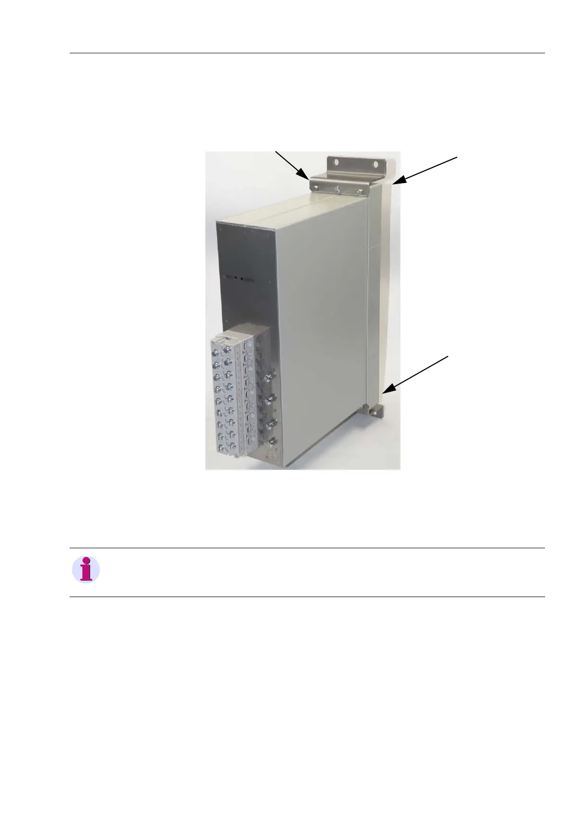
Screw the 2 Z angles included in the delivery to the upper and lower part of the
front cover using 2 M4 screws, respectively.
To do so, insert the screws into the bores on the front cover and screw the
angles tight. The 2 bores on the small side of the Z angles have M4 threads.
Fig. 8-2 Attaching the Z Angles to the Front Cover
Use 4 screws to fasten the device to the switch panel.
Wire the device as described in Chapter 8.4.
The terminal strip is accessible from the front for this type of assembly.
NOTE
Observe the dimensions and notes in Chapter 7.1.

Questions and Answers:

Question and Answer IconNeed help?

Do you have a question about the Siemens SIPROTEC 4 7XT7100-0 A00/EE Series and is the answer not in the manual?

Siemens SIPROTEC 4 7XT7100-0 A00/EE Series Specifications

General IconGeneral
BrandSiemens
ModelSIPROTEC 4 7XT7100-0 A00/EE Series
CategoryControl Unit
LanguageEnglish

Related product manuals