Information on Installation, Connection, and
Operation
When the 7UM85 is applied to protect explosion-proof motors, the following scenario must be considered: In
case of a device failure, the overcurrent protection is no longer guaranteed as protection against inadmissible
temperatures. The device failure is signaled by the internal standby relay via a break contact. This contact can
be used to shut down the machine or to bring the process into a secure state.
The 7UM85 can operate to ensure the highest safety only when the following conditions are fulfilled:
•
The circuit breaker with the undervoltage-tripping element is used.
•
The life contact of the 7UM85 is included in the trip circuit.
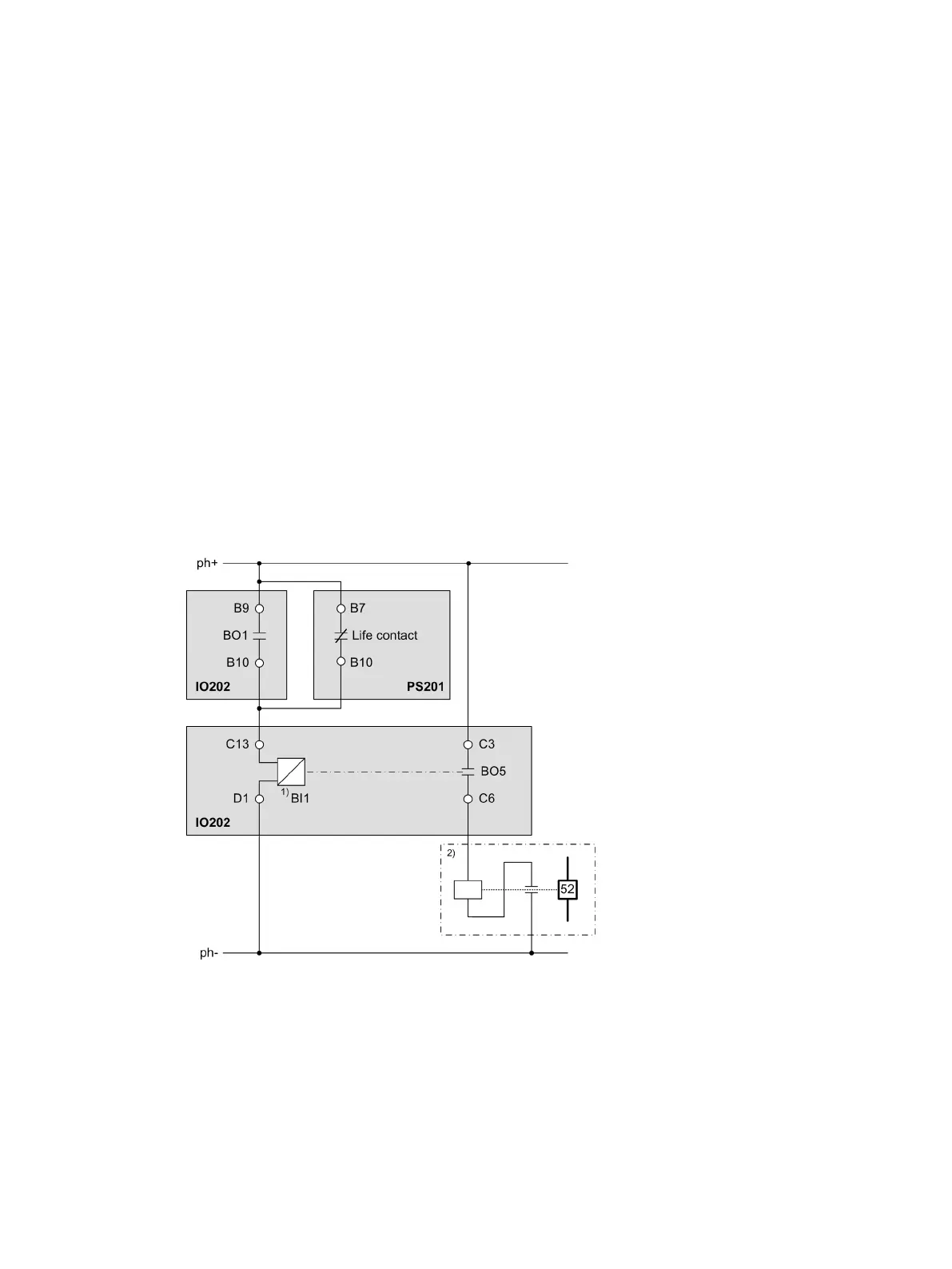
The following figure shows a connection diagram in which the trip signal is implemented via a binary input
and an additional standard relay of the 7UM85. This connection is required in order to meet all ATEX-related
safety requirements.
[lo_connection diagram_7SK85, 2, en_US]
Figure 6-1
Connection Diagram
(1) Binary input which is active without voltage
(2) Circuit breaker with undervoltage-tripping element
•
The trip command of the 7UM85 is configured to binary output BO1.
•
The break-contact element of the life contact and the make contact of BO1 are connected in parallel.
6
SIPROTEC 5, Additional Information on the Protection of Explosion-Proof Motors with Type of Protection Increased Safety e,
Manual
33
C53000-H5050-C078-1, Edition 03.2019

 Loading...


